4 layers39.3 × 63.8 mm
EMERSON'S HANDHELD GAME
Batterhead221/game_girl
game_girl is a custom ESP32-S3 handheld mini-arcade built around a monochrome OLED display, rotary encoder controls, button input, buzzer audio, and battery support.
25 parts

 Batterhead221/pocket_sprite
A custom ESP32-S3 handheld game console with a joystick, action button, TFT display, buzzer, battery power, custom PCB, and built-in mini games.
Pocket sprite is an open-source printed circuit board by Batterhead221, from the Batterhead221/pocket_sprite repository on GitHub. It is a 2-layer board of 125 × 46 mm with 18 parts on 20 nets, routed with 131 tracks and 52 vias.
It is built around the ESP32-S3, AO3400A and CMT-4023S-SMT-TR, with the DS04-254-2-01BK-SMT among its other parts. Its parts include 5 resistors, 3 diodes, 2 ICs, 2 switches and 1 capacitor. It belongs with the keyboards and input and power boards and the ESP32 boards of this library.


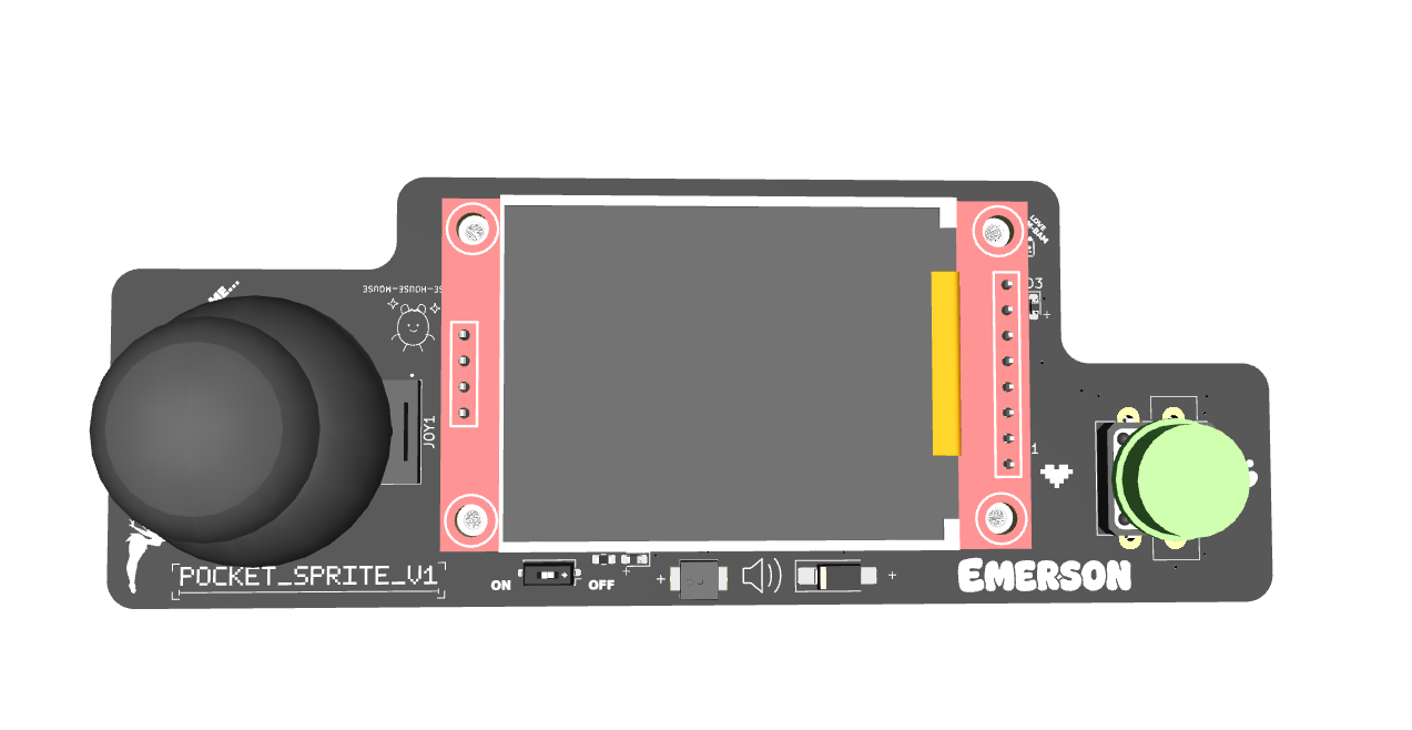
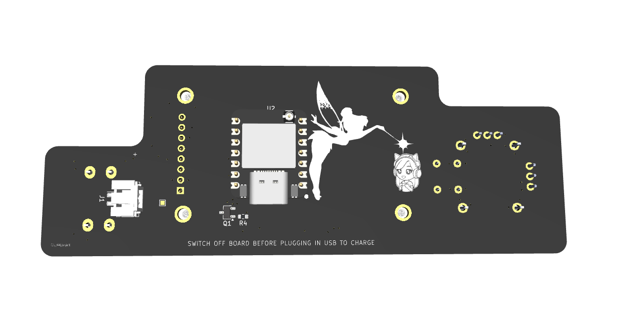
A custom ESP32-S3 handheld game console with joystick input, an action button, ST7735 color TFT display, buzzer audio, battery power, custom PCB artwork, and multiple built-in mini games.
POCKET_SPRITE is a compact original hardware project built around the Seeed Studio XIAO ESP32-S3 and a 1.8-inch ST7735 SPI TFT display. The board combines custom electronics, embedded firmware, pixel graphics, playful silkscreen art, and portable battery-powered hardware into a small handheld game device.
In progress. Breadboard input/display testing completed before the PCB version. Current hardware direction uses the XIAO ESP32-S3, joystick, 1.8-inch SPI TFT, A button, TFT backlight control, buzzer output, battery input through the XIAO BAT pads, and a switched 3.3V rail for game hardware.
Current firmware includes:
| Function | Part / Notes |
|---|---|
| MCU | Seeed Studio XIAO ESP32-S3 |
| Display | 1.8-inch ST7735 SPI TFT |
| Display driver | LovyanGFX |
| Input | Joystick + one A button |
| Audio | Buzzer driven from GPIO |
| Power | Battery connected to XIAO BAT pads |
| Switched rail | XIAO_3V3 → switch → +3V3_SW |
| Board role | Portable handheld game/demo board |
| XIAO Pin | Net | Function |
|---|---|---|
| D0 | JOY_SW | Joystick press |
| D1 | JOY_X | Joystick X analog |
| D2 | JOY_Y | Joystick Y analog |
| D3 | A_JUMP | A / jump button |
| D4 | CS | TFT chip select |
| D5 | DC | TFT data/command |
| D6 | RST | TFT reset |
| D7 | B-LITE | TFT backlight |
| D8 | SCK | TFT SPI clock |
| D9 | CHIRP | Buzzer drive |
| D10 | MOSI | TFT SPI MOSI |
| 3V3 | XIAO_3V3 | Regulated 3.3V from XIAO |
| GND | GND | Ground |
| BAT+ | XIAO_BAT+ | Battery positive |
| BAT- | XIAO_BAT- | Battery negative |
Breadboard joystick values measured during testing:
| Axis / Direction | Value / Behavior |
|---|---|
| X center | about 1970 |
| Y center | about 2020 |
| Deadzone | about 450 |
| UP | X low |
| DOWN | X high |
| LEFT | Y high |
| RIGHT | Y low |
Firmware should use calibration/deadzone handling instead of assuming perfect center values.
The display is a 1.8-inch ST7735 SPI TFT.
TFT CS    → D4
TFT DC    → D5
TFT RESET → D6
TFT BL    → D7 / B-LITE
TFT SCK   → D8
TFT MOSI → D10Joystick SW → D0
Joystick X → D1
Joystick Y → D2
A button → D3The joystick direction mapping from breadboard testing:
UP    → X low
DOWN  → X high
LEFT  → Y high
RIGHT → Y lowThe buzzer output is labeled CHIRP and is driven from D9.
D9 / CHIRP → buzzer driveIf the buzzer current is above the safe GPIO drive range, use a transistor or MOSFET driver instead of driving the buzzer directly from the XIAO GPIO.
The battery connects directly to the XIAO battery pads. The XIAO provides the regulated 3.3V rail used by the game hardware.
Battery → XIAO BAT pads
XIAO_3V3 → switch → +3V3_SW
+3V3_SW → joystick / display / buzzer support hardware
Battery support should follow the Seeed Studio XIAO ESP32-S3 battery/BAT pad guidance for a 1S LiPo setup.
Useful firmware modules:
Expected image paths for GitHub README rendering:
Outputs/
  IMG/
    3D-T.png
    3D-B.png
    SCHEMATIC.png
    L1-SIG.png
L2-GND.pngPOCKET_SPRITE is a low-voltage handheld electronics project. Verify battery polarity, switched power behavior, buzzer drive current, and display wiring before portable use.
Designed & Engineered by Brandon Shelly
| Qty | Value | Footprint | References |
|---|---|---|---|
| 3 | 1K | RESISTOR:R_0603_1608Metric | R2, R3, R5 |
| 2 | LED_0603 | DIODE:D_0603_1608Metric_Pad1.05x0.95mm_HandSolder | D1, D3 |
| 1 | 1.8_TFT_LCD_Display_Module | DISPLAY:SPI_DISPLAY | U1 |
| 1 | 100K | RESISTOR:R_0603_1608Metric | R4 |
| 1 | 100nF | CAPS:C_0603_1608Metric | C1 |
| 1 | 10K | RESISTOR:R_0603_1608Metric | R1 |
| 1 | AO3400A | SOT:TSOT-23 | Q1 |
| 1 | BAT_PAD | TestPoint:TestPoint_Pad_1.0x1.0mm | PAD1 |
| 1 | BUTTON | BUTTON_SWITCH:Push_Button_W12mm | SW3 |
| 1 | CMT-4023S-SMT-TR | BUZZER:CUI_CMT-4023S-SMT-TR | BZZ1 |
| 1 | DS04-254-2-01BK-SMT | BUTTON_SWITCH:SW_DIP_SPSTx01_Slide_Copal_CHS-01A_W5.08mm_P1.27mm_JPin | SW1 |
| 1 | D_Schottky | DIODE:D_SMA_Handsoldering | D2 |
| 1 | ESP32-S3 | MODULE:XIAO-ESP32_THROUGH_HOLE_PINS | U2 |
| 1 | JOYSTICK | JOYSTICK:XDCR_COM-09032_MODED | JOY1 |
| 1 | Screw_Terminal_01x02 | JST_PH:JST_PH_B2B-PH-SM4-TB_1x02-1MP_P2.00mm_Vertical | J1 |
It measures 125 × 46 mm and has 2 copper layers, 1.6 mm thick.
18 parts, built around the ESP32-S3, AO3400A, CMT-4023S-SMT-TR and DS04-254-2-01BK-SMT. The full list of its parts is on this page, with links to each part's symbol and footprint where PCBKit's library has them.
From the Batterhead221/pocket_sprite repository on GitHub, at the commit this page was made from: the board is ECAD/pocket_sprite.kicad_pcb and its schematic ECAD/pocket_sprite.kicad_sch. PCBKit opens the board in the browser, with nothing to install.
Its repository states no licence, so its author keeps all rights: ask Batterhead221 before reusing the design.
Batterhead221/game_girl
game_girl is a custom ESP32-S3 handheld mini-arcade built around a monochrome OLED display, rotary encoder controls, button input, buzzer audio, and battery support.


aeonSolutions/AeonLabs-AI-Volvo-MKII-Open-Hardware
Volvo MKII Open Hardware