
2 layers83.8 × 33.7 mm
ElectricFenceMonitor
jgOhYeah/Farm-PJON-LoRa-network
Code relating to a small LoRa network for remote monitoring and control
30 parts1MIT

 jgOhYeah/Farm-PJON-LoRa-network1
Code relating to a small LoRa network for remote monitoring and control
GateMonitorLayout is an open-source printed circuit board by jgOhYeah, from the jgOhYeah/Farm-PJON-LoRa-network repository on GitHub, published under the MIT licence. It is a 2-layer board of 113 × 44.5 mm with 27 parts on 28 nets, routed with 140 tracks and 48 vias.
It is built around the IRLB8721PBF. Its parts include 11 resistors, 5 connectors, 4 capacitors, 3 ICs and 3 diodes. It belongs with the radio and wireless boards of this library.
Code relating to a small LoRa network for remote monitoring and control. This is a work in progress.
Currently an Arduino Nano and 40x2 Alphanumeric LCD, thinking of swapping the nano with a raspberry pi to allow better data logging and display over an ip network. This is still a work in progress. Needs the lcd graph library I have written to draw graphs on alpha numeric lcds. It is also a work in progress. This can be found here.
Currently a work in progress and have not uploaded the files to Github yet, but uses a python script to interface with an SX1278 LoRa module and translate this into MQTT to pass to a Thingsboard server running on the pi.
This branch of the PyLora library is required to talk to the radio module as it has been adapted for python 3.
This is code currently in use in a device that is monitoring battery charge in a remote solar powered electric fence. It sends a packet with the battery voltage once every few minutes and listens for an incoming packet for a set time after each tansmission. The incoming packet can tell the device to turn the fence on or off or control other aspects of the radio link such as disabling transmissions until another incoming packet enables them or requesting the current status be resent.
I used KiCad to plan a layout on veroboard so that I knew there was room for everything and I didn't end up cutting the wrong tracks. The yellow circles and lines in layer Eco2.User are where tracks should be cut. The KiCad files can be found here.
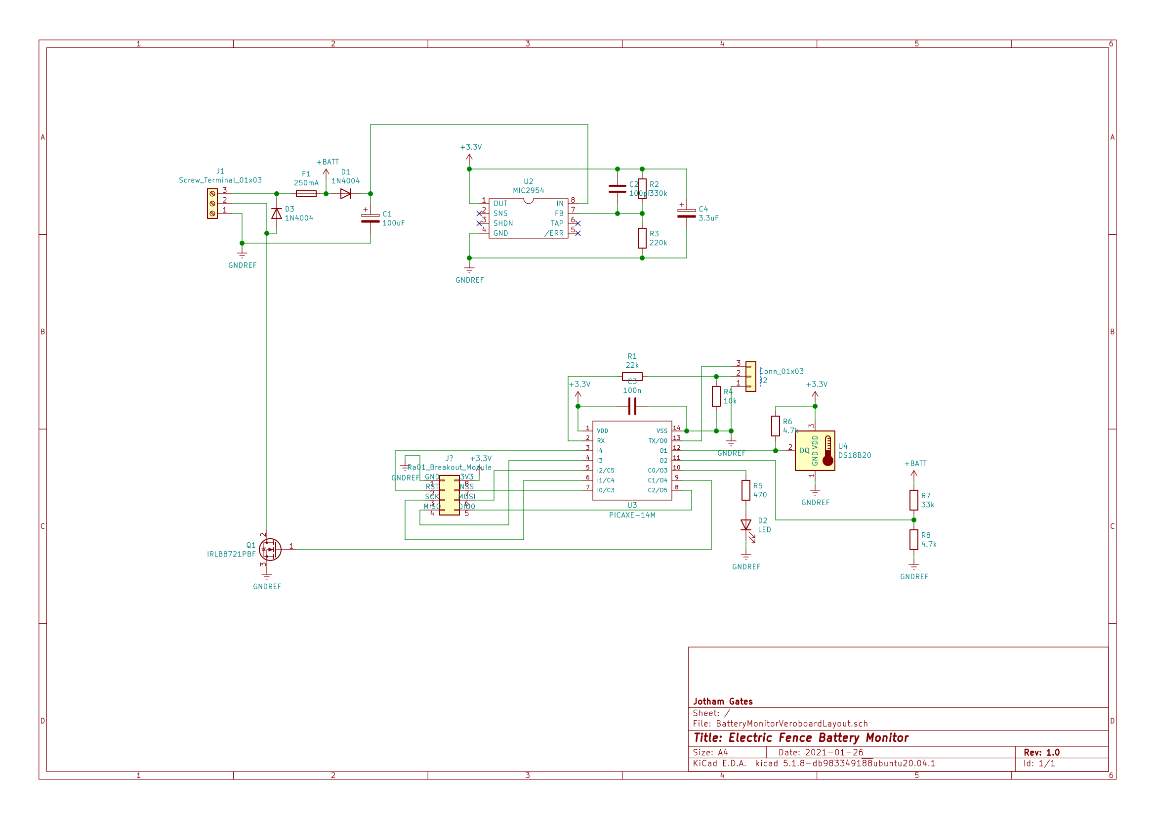
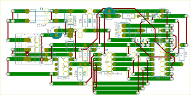
This is a work in progess and as such it is only temperarily mounted in the shed, although you know what they say about temporary things :).
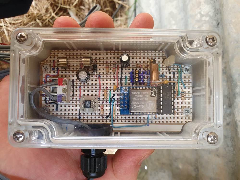
Battery voltage monitor before the mosfet was added for controlling the fence and an external antenna to improve range.
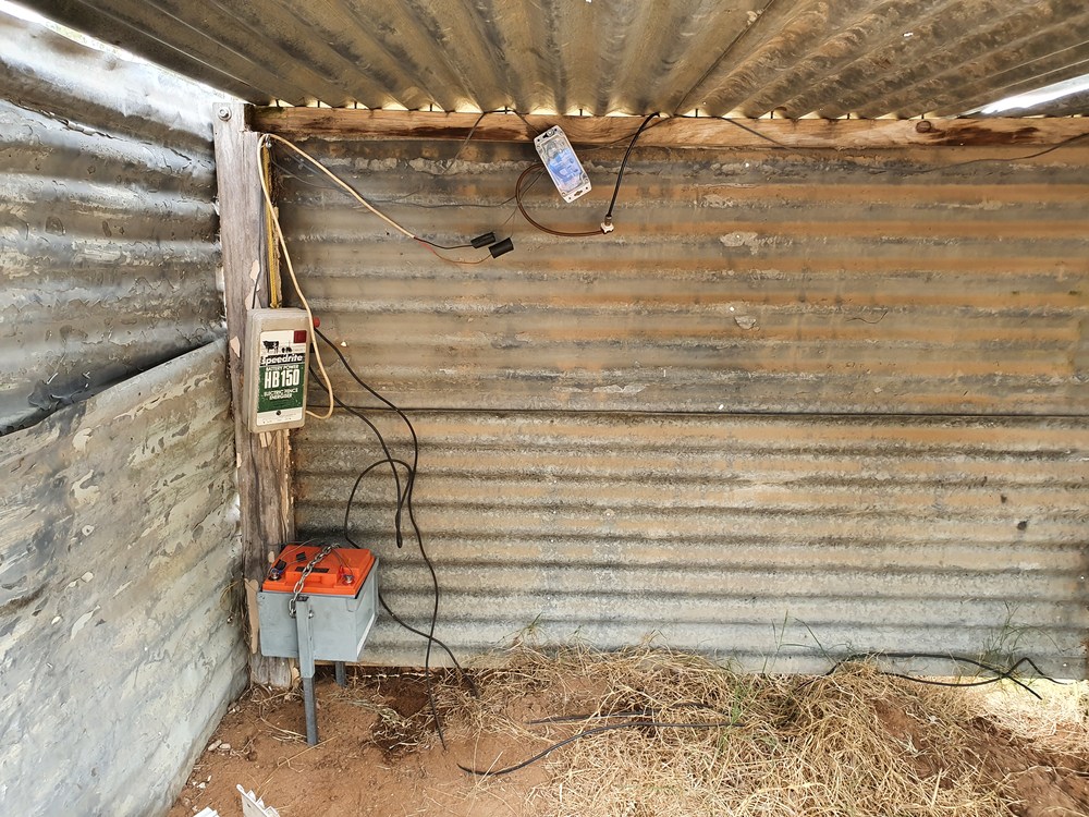
The shed and setup of the battery monitor.
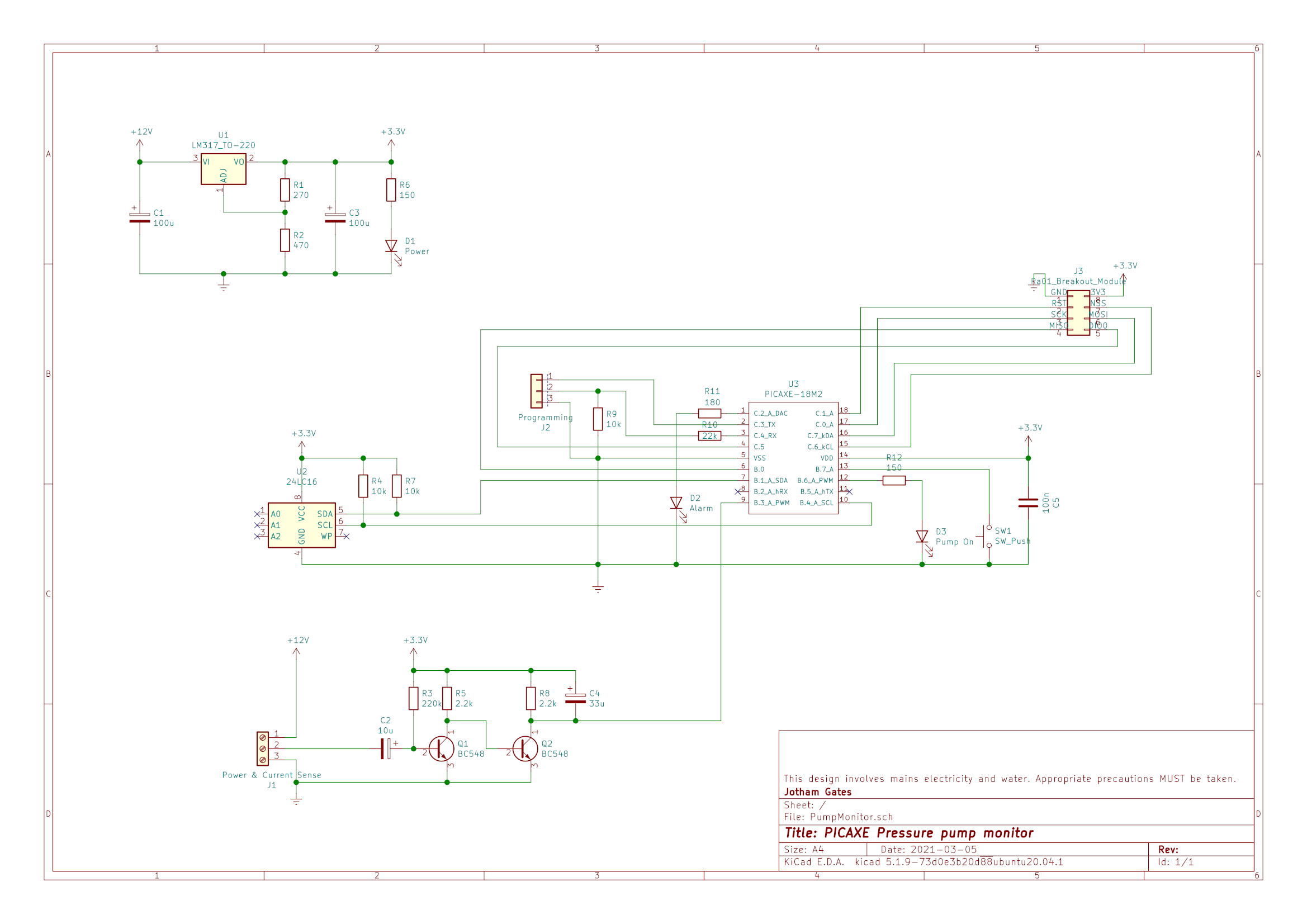
This is a monitor for the main pressure pump of the farm that allows the on time of the pump to be measured to hopefully detect leaks sooner rather than later.
The monitor currently operates by timing how many half seconds the pump is on in a half hour block. At the end of each block, the monitor saves the time to a circular buffer stored in an EEPROM chip, calculates the average on time for all values in the chip and transmits the time on in the last half hour as well as the average on time as a LoRa radio packet using the PJON protocol for addressing.
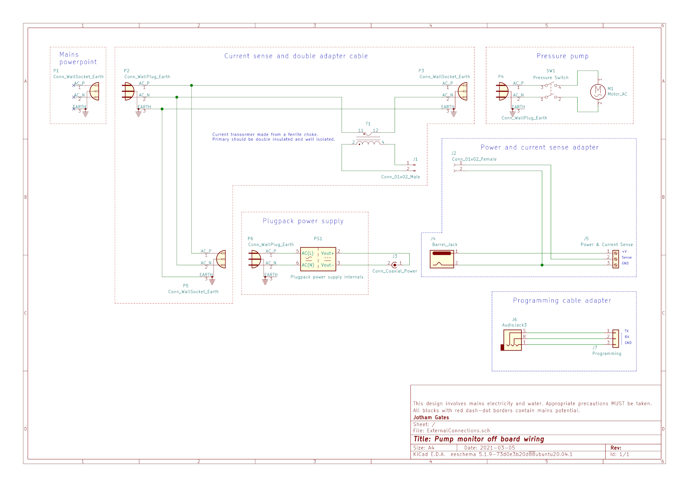
To detect when the pump is running, a simple current transformer was made by winding the neutral wire in a mains extension lead around a filtering choke from an old power supply. Some electrical spaghetti insulation was placed over the neutral wire to ensure that there are multiple layers of insulation between the primary coil formed by the neutral wire and the secondary coil formed by the ~100 turns of enamal copper wire originally on the choke. This is amplified and rectified by a pair of transistors on the pump monitor circuit board. The current transformer is not particulary linear and the amplifier was designed to output a digital signal, meaning that precise current measurement is not currently an option :). Having said that, the system does seem to be quite reliable in detecting when the pump is on and off.
Using an XL2416CP 16kb EEPROM chip, approximately 20 days worth, or 1023 values can be stored at a time.
The software to handle the circular buffer and talk to the radio module take up most of the program space. Strings to print using sertxd are stored in table memory. To avoid having to calculate string lengths and memory locations, I have been working on an extension to this python preprocessor, currently in this branch that will automatically add and call the correct subroutines whenever a ;#sertxd directive is encountered. If you don't want to use this, you can use the compiled.bas file that will have and the ;#sertxd directives correctly substituted, or use the standard PICAXE Programming Editor 6 that will ignore them as a comment, leaving code that will work, but with cryptic numbers being all that is printed to the serial console.
As with the Battery monitor above, I planned out a layout using Kicad before printing a template and using this to cut tracks and place jumper wires and components in the required places. The Kicad files can be found here.
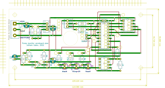
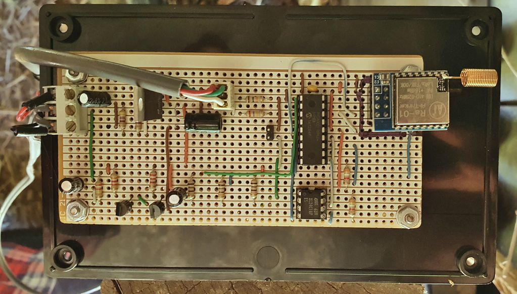
Bird's eye view of the circuit.
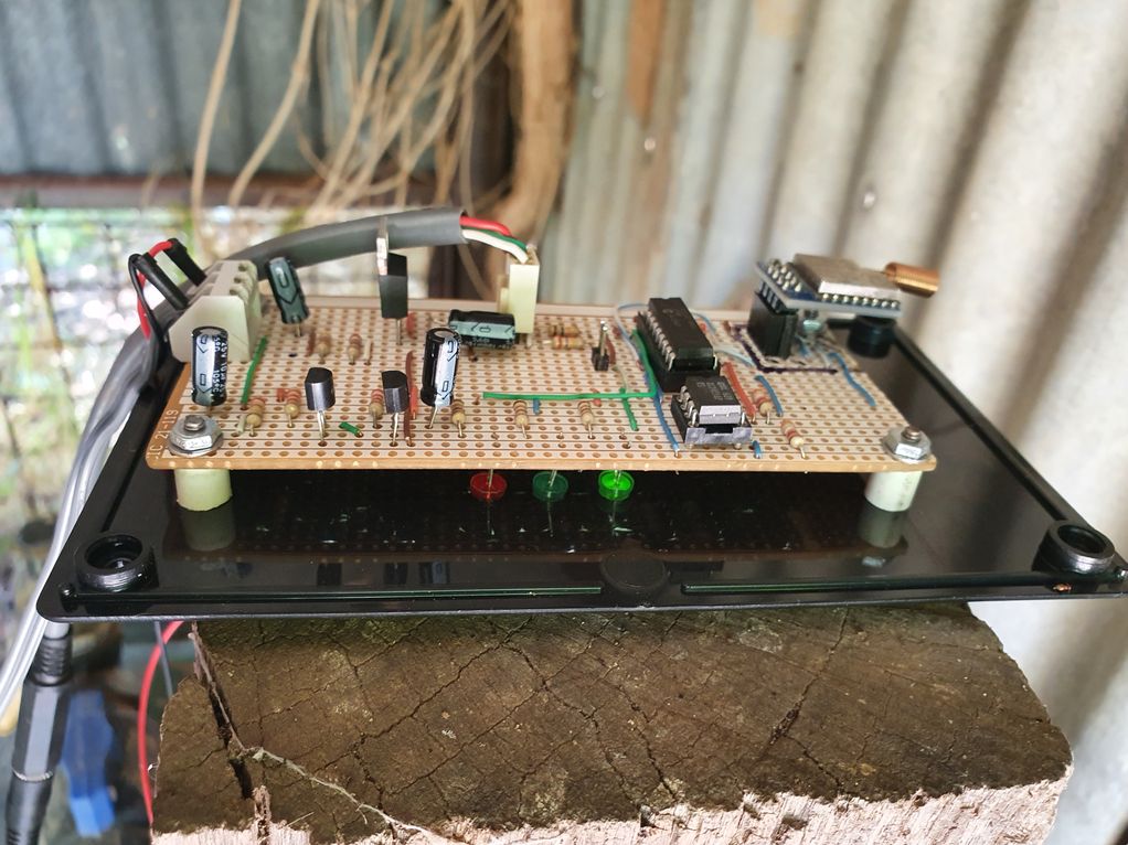
View of the monitor circuit board showing the placement of the indicator LEDs.
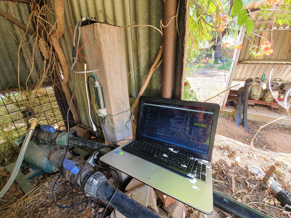
Testing and software development showing the pump and current transformer (inside the green and black poly pipe extension of a mains socket).
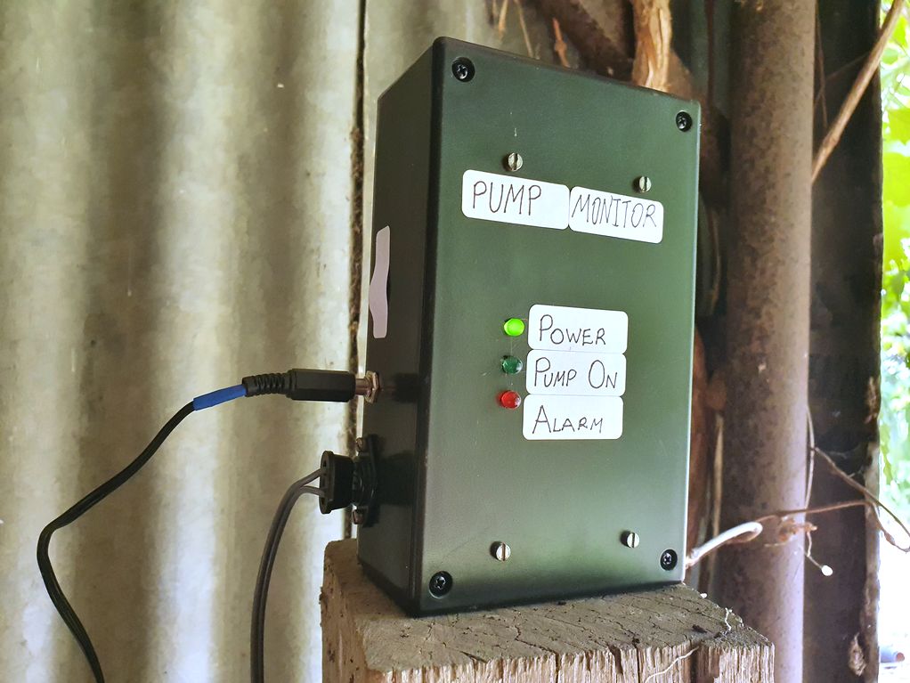
The pump monitor in its box.
| Qty | Value | Footprint | References |
|---|---|---|---|
| 2 | 1N4004 | Diode_THT:D_DO-41_SOD81_P5.08mm_Vertical_AnodeUp | D1, D2 |
| 1 | 100n | Capacitor_THT:C_Axial_L3.8mm_D2.6mm_P12.50mm_Horizontal | C4 |
| 1 | 100pF | Capacitor_THT:C_Disc_D7.0mm_W2.5mm_P5.00mm | C2 |
| 1 | 100u | Capacitor_THT:C_Rect_L13.0mm_W6.0mm_P10.00mm_FKS3_FKP3_MKS4 | C1 |
| 1 | 10k | Resistor_THT:R_Axial_DIN0207_L6.3mm_D2.5mm_P10.16mm_Horizontal | R1 |
| 1 | 22k | Resistor_THT:R_Axial_DIN0207_L6.3mm_D2.5mm_P5.08mm_Vertical | R2 |
| 1 | 270k | Resistor_THT:R_Axial_DIN0207_L6.3mm_D2.5mm_P10.16mm_Horizontal | R4 |
| 1 | 3.3u | Capacitor_THT:CP_Radial_D8.0mm_P5.00mm | C3 |
| 1 | 33k | Resistor_THT:R_Axial_DIN0207_L6.3mm_D2.5mm_P5.08mm_Vertical | R6 |
| 1 | 4.7k | Resistor_THT:R_Axial_DIN0207_L6.3mm_D2.5mm_P7.62mm_Horizontal | R11 |
| 1 | 4.7k | Resistor_THT:R_Axial_DIN0207_L6.3mm_D2.5mm_P10.16mm_Horizontal | R9 |
| 1 | 4.7k | Resistor_THT:R_Axial_DIN0204_L3.6mm_D1.6mm_P2.54mm_Vertical | R7 |
| 1 | 4.7k | Resistor_THT:R_Axial_DIN0207_L6.3mm_D2.5mm_P5.08mm_Vertical | R8 |
| 1 | 470 | Resistor_THT:R_Axial_DIN0207_L6.3mm_D2.5mm_P10.16mm_Horizontal | R5 |
| 1 | 470k | Resistor_THT:R_Axial_DIN0207_L6.3mm_D2.5mm_P5.08mm_Vertical | R3 |
| 1 | AHT20 temperature sensor | Connector_PinSocket_2.54mm:PinSocket_1x04_P2.54mm_Vertical | J4 |
| 1 | Conn_01x03 | Connector_Molex:Molex_KK-254_AE-6410-03A_1x03_P2.54mm_Vertical | J2 |
| 1 | Hall effect | TerminalBlock:TerminalBlock_Altech_AK300-3_P5.00mm | J5 |
| 1 | IRLB8721PBF | Package_TO_SOT_THT:TO-220-3_Vertical | Q1 |
| 1 | LDR07 | OptoDevice:R_LDR_7x6mm_P5.1mm_Vertical | R10 |
| 1 | LED | LED_THT:LED_D5.0mm | D3 |
| 1 | MIC2954 | Package_DIP:DIP-8_W7.62mm_Socket_LongPads | U3 |
| 1 | PICAXE-18M2 | Package_DIP:DIP-18_W7.62mm_Socket_LongPads | U2 |
| 1 | PIR sensor | Connector_PinHeader_2.54mm:PinHeader_1x03_P2.54mm_Vertical | J3 |
| 1 | Ra01_Breakout_Module | Package_DIP:DIP-8_W7.62mm_Socket_LongPads | U1 |
| 1 | Screw_Terminal_01x03 | TerminalBlock:TerminalBlock_Altech_AK300-3_P5.00mm | J1 |
jgOhYeah/Farm-PJON-LoRa-network
Code relating to a small LoRa network for remote monitoring and control

jgOhYeah/Farm-PJON-LoRa-network
Code relating to a small LoRa network for remote monitoring and control

jgOhYeah/Farm-PJON-LoRa-network
Code relating to a small LoRa network for remote monitoring and control

jgOhYeah/Farm-PJON-LoRa-network
Code relating to a small LoRa network for remote monitoring and control

KoffeinFlummi/rustbucket
Access your car's diagnostics with a BeagleBone Blue and Rust.


stelioskat/esp8266-led-dimmer
Wifi enabled LED strip dimmer that is controlled using MQTT messages.


chl33/Dough133
A temperature-controlled container for proofing and fermenting soughdough


Adamibus/ESPAtomizer-iOS
This is a minimal KiCad 6/7 project skeleton. Open ESPAtomizer.kicadpro in KiCad.
It measures 113 × 44.5 mm and has 2 copper layers, 1.6 mm thick.
27 parts, built around the IRLB8721PBF. The full list of its parts is on this page, with links to each part's symbol and footprint where PCBKit's library has them.
From the jgOhYeah/Farm-PJON-LoRa-network repository on GitHub, at the commit this page was made from: the board is GateMonitor/GateMonitorLayout/GateMonitorLayout.kicad_pcb and its schematic BatteryVoltageMonitor/BatteryMonitorVeroboardLayout/BatteryMonitorVeroboardLayout.kicad_sch. PCBKit opens the board in the browser, with nothing to install.
Its repository publishes it under the MIT licence: you may reuse it on that licence's terms (keep the author's notice, and for a copyleft licence share your changes alike).