
2 layers99.1 × 99.1 mm

 KoffeinFlummi/rustbucket60
Access your car's diagnostics with a BeagleBone Blue and Rust.
Beaglebone obd is an open-source printed circuit board by KoffeinFlummi, from the KoffeinFlummi/rustbucket repository on GitHub, published under the GPL-3.0 licence. It is a 2-layer board of 50.8 × 28.6 mm with 20 parts on 12 nets, routed with 69 tracks and 0 vias.
It is built around the IRLB8721PBF. Its parts include 7 resistors, 6 transistors and 1 capacitor.
Access your car's diagnostics via the OBD2 connector with a BeagleBone Blue and Rust (and maybe some MOSFETs). This was inspired by Marcelo Sacchetin's post about using the BeagleBone Blue's integrated CAN bus transceiver. If you want to read the diagnostics for older vehicles, things are a bit more complicated than that. For older VWs for instance, you will need to talk to the vehicle's K line using the KWP1281 protocol. This requires additional hardware to convert the BeagleBone's 3.3V logic level to 12V.
This was developed on/for the BeagleBone Blue, but the K & L line protocols should be just as usable on a BeagleBone Black. As far as I know, accessing the CAN bus on the Black requires the addition of a CAN transceiver.

Hooking stuff up to your vehicle's OBD2 connector can lead to anything from blown fuses to broken hardware. There are reports online of attempting to communicate with certain VW airbag controllers via KWP1281 bricking them. There are also apparently instances of clearing the fault codes using KWP1281 leading to deployed airbags for certain errors.
I have tested the software and hardware described here successfully on some vehicles/ECUs (see below). However, I cannot provide any guarantee that using this will not cause permanent damage to you or your vehicle. Proceed at your own risk. Also, don't fuck with airbags please.
| Protocol | Used Lines | Implemented | Notes |
|---|---|---|---|
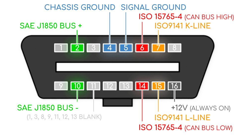
| CAN Bus / ISO 15765 | CAN High & CAN Low | ✓ | Used by almost any modern vehicle. No additional hardware needed; The BB Blue's CAN transceiver can be connected directly to the OBD port's CAN lines. |
| KWP1281 | K Line | ✓ | Not an official OBD2 protocol, used on older VAG (VW & friends) cars. Returned codes are not official OBD2 DTCs. |
| ISO 9141 | K & L Line | ✗ | Apparently similar to KWP1281, but an official OBD2 protocol. Not implemented, but technically supported by hardware described below. |
| KWP2000 / ISO 14230 | K & L Line | (✓) | Implemented at least partially (K line init only, no fast init). OBD2 commands not implemented, but some VAG specific stuff has been tested (see below). |
There are some more OBD2 protocols, that apparently are mostly used on American vehicles. I have not considered these, and the hardware required seems quite different.
Note that the above is my understanding, this whole field is a giant mess of standards and acronyms.
| Vehicle/ECU | Protocol | Baud/Bit Rate | Notes |
|---|---|---|---|
| VW Golf Mk4 (1J), 2001 | KWP1281 | 10400,9600,1200 | All ECUs except ESP and airbag controller. See script and sample output. |
| VW Golf Mk4 (1J), 2001 | KWP2000 | 10400 | ESP Mk60 controller. Reading & clearing DTCs only. |
| VW Golf Mk7 (AUV), 2014 | CAN | 500000 | Most things work, but multi-frame messages (VIN, more than 2 DTCs) do not. Might require modifications to flow control messages. |
| CAN | 500000 | CAN bus is active, but does not respond to OBD2 queries. I did not spend much time on this, might require some sort of initialization. | |
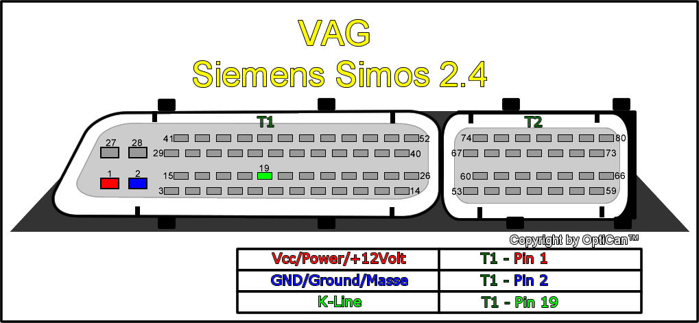
| Siemens SIMOS2.1B ECU | KWP1281 | 9600 | Pinout (also has a 500kbps CAN bus on pins 29 (L) & 31 (H), but this is not used for diagnostics and does not respond to OBD2 queries) |
| Bosch EDC16U34 ECU | CAN | 500000 | Pinout |
You can compile this directly on the BeagleBone, but the compilation times can be annoying, so the project is set up for cross-compilation. You will have to add the armv7-unknown-linux-gnueabihf target using rustup (You'll also need a version of GCC compiled for arm-linux-gnueabihf for linking. Consult your OS' package manager.):
$ rustup target add armv7-unknown-linux-gnueabihf
$ cargo build --release
Then, copy the executable to the BeagleBone.
See rustbucket -h for usage.
The program contains modes for testing the hardware and simulating a car so you can test your hardware using two BeagleBones instead of a car. However, the best way to test is to get yourself a used ECU off of eBay. These can be bought relatively cheaply for older cars (I paid less than 20€ for each of the ECUs I tested with). See references below for some ECU pinouts.

When testing the CAN protocol with two BeagleBone Blues, you should add a terminating resistor (I used 100Ω) between the CAN lines. The R104 120Ω terminating resistor is not populated from the factory on the BB Blue, and with an unterminated CAN bus you will have problems with the higher bit rates (such as the default 500kbps). This may also apply to some desktop ECUs, but the ones I tested with had 66Ω internal resistors.
For the CAN bus, you can simply connect the BeagleBone Blue's CAN lines directly to the OBD2 connector (On the BeagleBone Black, you'll have to connect a CAN transceiver). For the K Line, the 3.3V logic level of the BeagleBone's UART1 bus will have to be converted to the 12V used on the K line, and vice versa.
I tried to implement this design for a bi-directional logic level converter using a single N-channel MOSFET, but I couldn't figure out how to do so while making sure that the BeagleBone pins don't sink too much current. Since I had a bunch of N-channel MOSFETs lying around anyway, I just went with this horrendously inefficient design using 2 MOSFETs for reading and writing respectively:

The BeagleBone's UART1 bus (TX: P9.24, RX: P9.26) is used for writing and reading the K line. The schematic also includes the same setup for writing to the L line, but this is not used in software ATM. Q3 has a gate voltage of 12V, the rest is 3.3V.
If you actually know what you're doing electronics-wise, you can probably come up with something better/more efficient. Contributions appreciated.
I used an IRFZ24NPbF for Q3 and IRLB8748PbF for the others since I had them around. If you're buying components specifically for this there are probably better options, and you may want to go with SMD stuff (or just a better design in general). If you are using TO-220 (G-D-S) components like I did, you may also find the terrible PCB I designed useful. I also have some left over, so let me know if you want one.
KiCAD project (schematic + PCB + Gerber files) can be found here.
| Qty | Value | Footprint | References |
|---|---|---|---|
| 6 | 1K | Resistor_THT:R_Axial_DIN0207_L6.3mm_D2.5mm_P7.62mm_Horizontal | R1, R2, R4, R5, R6, R7 |
| 6 | IRLB8721PBF | Package_TO_SOT_THT:TO-220-3_Vertical | Q1, Q2, Q3, Q4, Q5, Q6 |
| 1 | 10K | Resistor_THT:R_Axial_DIN0207_L6.3mm_D2.5mm_P7.62mm_Horizontal | R3 |
| 1 | 47u | Capacitor_THT:CP_Radial_D5.0mm_P2.00mm | C1 |
| 1 | LOGO | kicad:ferris | G*** |
The 15 most common of 20 parts.

stelioskat/esp8266-led-dimmer
Wifi enabled LED strip dimmer that is controlled using MQTT messages.


chl33/Dough133
A temperature-controlled container for proofing and fermenting soughdough


Adamibus/ESPAtomizer-iOS
This is a minimal KiCad 6/7 project skeleton. Open ESPAtomizer.kicadpro in KiCad.

It measures 50.8 × 28.6 mm and has 2 copper layers, 1.6 mm thick.
20 parts, built around the IRLB8721PBF. The full list of its parts is on this page, with links to each part's symbol and footprint where PCBKit's library has them.
From the KoffeinFlummi/rustbucket repository on GitHub, at the commit this page was made from: the board is kicad/beaglebone_obd.kicad_pcb. PCBKit opens the board in the browser, with nothing to install.
Its repository publishes it under the GPL-3.0 licence: you may reuse it on that licence's terms (keep the author's notice, and for a copyleft licence share your changes alike).