
2 layers58.4 × 50.8 mm
Haible tau phaser plug in board
JordanAceto/VCF_plug_in_boards
Various small synthesizer Voltage Controlled Filter pcbs
140 parts11CC-BY-4.0

 jensma-de/MM58167-ISA-RTC9
RTC module for the ISA slot. With schematics, project files in kicad and open source software to drive the clock.
MM58167-ISA RTC is an open-source printed circuit board by jensma-de, from the jensma-de/MM58167-ISA-RTC repository on GitHub. It is a 2-layer board of 89.3 × 50 mm with 29 parts on 94 nets, routed with 522 tracks and 168 vias.
It is built around the 74LS245SC, 74HC04D and 1N5225B, with the 2N2222A and 2N2907A among its other parts. Its parts include 8 capacitors, 5 resistors, 5 ICs, 3 diodes and 2 transistors.


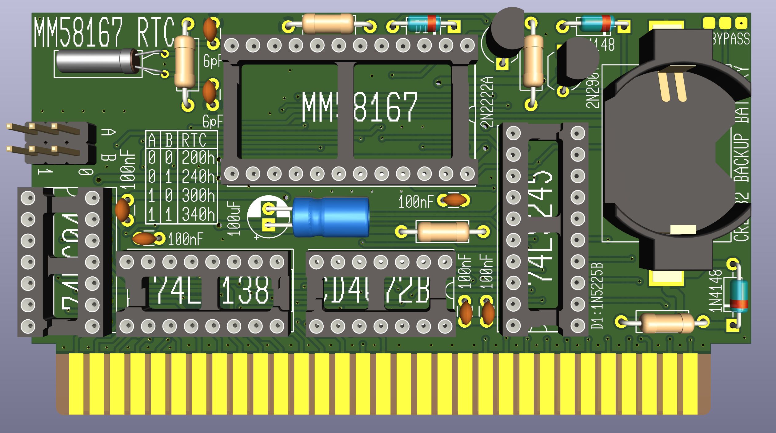
A 8bit real time clock for old computers. Keeps the time when the computer is shut down. Fully covered address bus to prevent conflicts. The backup battery should theoretically last for about six years.
Yes, there are many more modern RTC's out there. I made this just for fun and with parts that were readily available back in the 80s. I like to keep things period correct 😉
First set the jumpers for the RTC. You can choose between 200h, 240h, 300h and 340h.
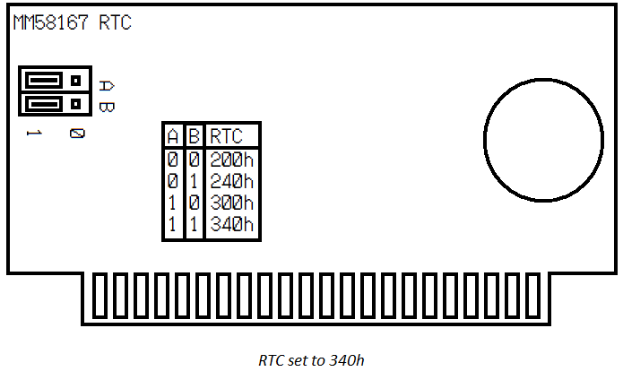
Plug the card into a free ISA slot, either 8bit or 16bit.
Download the control prgram and put it on your PC:
Control program: MM58167.EXE (Source: MM58167.BAS)
Alternative German version:
Control program: MM58167_GER.EXE (Source: MM58167_GER.BAS)
Next, have a look at the usage description:
Usage:
------

MM58167.EXE ADDRESSh SET|GET [VERBOSE] [FORCE] [NOEX]

Adressh:   The address of the RTC, set by jumpers on the PCB, e.g. 240h
SET|GET:   Sets the RTC to the system clock and vise versa.
[VERBOSE]: Outputs some information.
[FORCE]:   Force given address without checking for plausible RTC data.
[NOEX]:    Don't export the time to C:\MM581.RTC.
           The file is needed to update the year automatically.

Example:
To write the system time to the RTC, setup at 300h:
MM58167.EXE 300h SET

--------------------------------------------------------
Credits to:
github.com/mrehkopf/ & github.com/Sciurus68k/

Project page:
github.com/jensma-de/MM58167-ISA-RTC/
At first you need to set the current time and date to the clock:
dateAfter this command you can set the date interactively. Next up is the time:
timeSame interactive configuration here. Next up you put your time and date into the RTC (assuming you configured it for adress 340h):
MM58167.EXE 340h SETNow the RTC is set and should, if you put in a CR2032 coin cell into it, keep the time.
To read the date and time from the RTC to update your system on startup, add this to your C:\AUTOSTART.BAT:
MM58167.EXE 340h GETThat's it!
Only if you're having problems with the interrupt output: cut the trace between the two pads of the jumper in the top left corner of the pcb. Then close the center and the right pad.
Yes. Just make sure your OS can handle dates after 1999!
That's right. In order increment the year automatically the MM58167.EXE offloads some information to C:\MM581.RTC. If you don't want this for some reason you can disable it with the NOEX argument.
Downside to all of this is that you have to start your computer at least once in two years. But seriously - if you boot up your PC that rarely you might want to remove the time keeping battery anyways :)
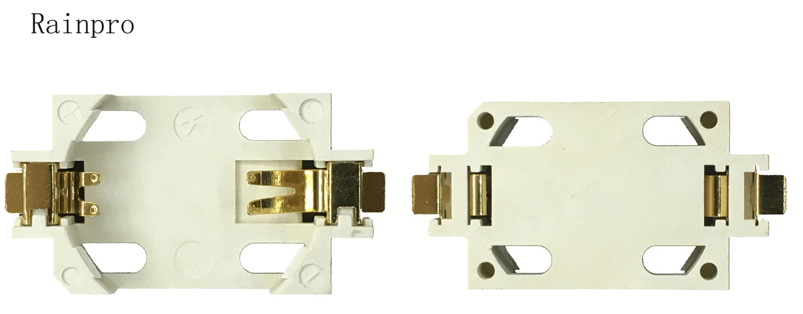
Note for the battery holder: The holder I used is just labeled "Rainpro". No idea about the exact model. Should be a very common CR2032 battery holder, though. Here's a picture of the listing:
Alternatively you can download and check out the interactive BOM: iBOM
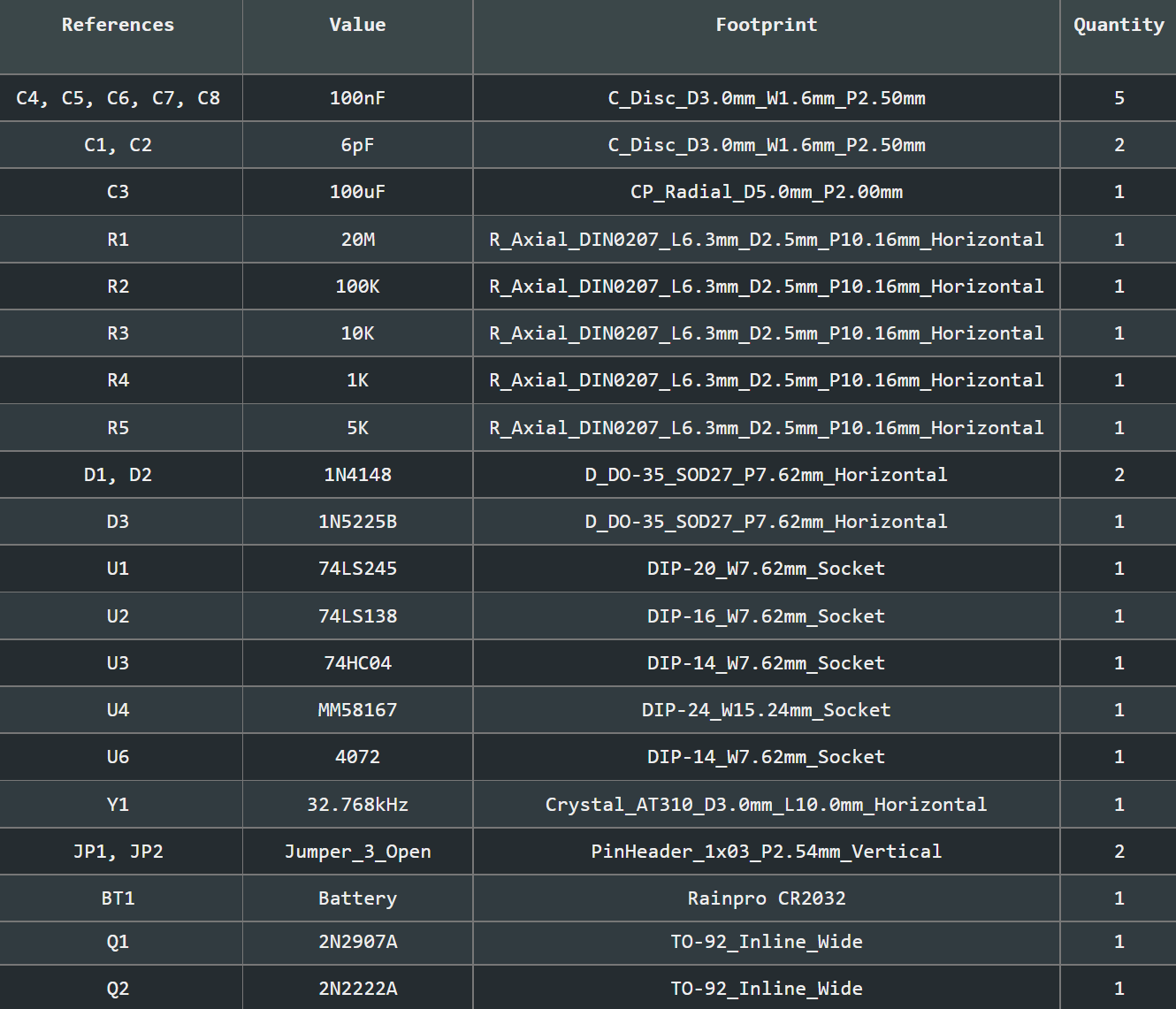
| Qty | Value | Footprint | References |
|---|---|---|---|
| 5 | 100nF | Capacitor_THT:C_Disc_D3.0mm_W1.6mm_P2.50mm | C4, C5, C6, C7, C8 |
| 2 | 1N4148 | Diode_THT:D_DO-35_SOD27_P7.62mm_Horizontal | D1, D2 |
| 2 | 6pF | Capacitor_THT:C_Disc_D3.0mm_W1.6mm_P2.50mm | C1, C2 |
| 2 | Jumper_3_Open | Connector_PinHeader_2.54mm:PinHeader_1x03_P2.54mm_Vertical | JP1, JP2 |
| 1 | 100K | Resistor_THT:R_Axial_DIN0207_L6.3mm_D2.5mm_P10.16mm_Horizontal | R2 |
| 1 | 100uF | Capacitor_THT:CP_Radial_D5.0mm_P2.00mm | C3 |
| 1 | 10K | Resistor_THT:R_Axial_DIN0207_L6.3mm_D2.5mm_P10.16mm_Horizontal | R3 |
| 1 | 1K | Resistor_THT:R_Axial_DIN0207_L6.3mm_D2.5mm_P10.16mm_Horizontal | R4 |
| 1 | 1N5225B | Diode_THT:D_DO-35_SOD27_P7.62mm_Horizontal | D3 |
| 1 | 20M | Resistor_THT:R_Axial_DIN0207_L6.3mm_D2.5mm_P10.16mm_Horizontal | R1 |
| 1 | 2N2222A | Package_TO_SOT_THT:TO-92_Inline_Wide | Q2 |
| 1 | 2N2907A | Package_TO_SOT_THT:TO-92_Inline_Wide | Q1 |
| 1 | 32.768kHz | Crystal:Crystal_AT310_D3.0mm_L10.0mm_Horizontal | Y1 |
| 1 | 4072 | Package_DIP:DIP-14_W7.62mm_Socket | U6 |
| 1 | 5K | Resistor_THT:R_Axial_DIN0207_L6.3mm_D2.5mm_P10.16mm_Horizontal | R5 |
| 1 | 74HC04 | Package_DIP:DIP-14_W7.62mm_Socket | U3 |
| 1 | 74LS138 | Package_DIP:DIP-16_W7.62mm_Socket | U2 |
| 1 | 74LS245 | Package_DIP:DIP-20_W7.62mm_Socket | U1 |
| 1 | Battery | Ayvi:Rainpro CR2032 | BT1 |
| 1 | Bus_ISA_8bit | Ayvi:BUS_AT | BUS1 |
| 1 | Jumper_3_Bridged12 | Ayvi:jumper_3 | JP3 |
| 1 | MM58167 | Package_DIP:DIP-24_W15.24mm_Socket | U4 |
JordanAceto/VCF_plug_in_boards
Various small synthesizer Voltage Controlled Filter pcbs


welzel-online/WiFi-VirtDisk
The WiFi-VirtDisk is a network-based storage solution that replaces or supplements the classic SD card approach. The hardware consists of an ESP8266 (D1 mini), which is connected to the SPI port (SD card).

MCMarcusAntony/iBOLIT-1.5
Tools added to this board are: - Logic probe included on Top three pin connector. - Lighting and acoustic signals to identify HIGH and LOW status.

morris6/Modulo-Two_ARINC-429_Converter
Converting a Modulo-Two Serial Stream to Arinc-429 Serial Words

electricalhog/Discrete_Opamp
Off-the-shelve based FET input opamp designed in ECE5204 and brought to PCB

UAA-F14/PCBs-Design
Power electronics PCB coursework — SCR controller, buck converter, Class D amplifier, DC-AC inverter, and a protected power supply Resources
It measures 89.3 × 50 mm and has 2 copper layers, 1.6 mm thick.
29 parts, built around the 74LS245SC, 74HC04D, 1N5225B and 2N2222A. The full list of its parts is on this page, with links to each part's symbol and footprint where PCBKit's library has them.
From the jensma-de/MM58167-ISA-RTC repository on GitHub, at the commit this page was made from: the board is main/main.kicad_pcb and its schematic main/main.kicad_sch. PCBKit opens the board in the browser, with nothing to install.
Its repository states no licence, so its author keeps all rights: ask jensma-de before reusing the design.