Skip to the content
2 layers58.4 × 50.8 mmHaible tau phaser plug in board, the printed circuit board in 3D

Haible tau phaser plug in board

JordanAceto/VCF_plug_in_boards11

Various small synthesizer Voltage Controlled Filter pcbs

Size
58.4 × 50.8 mm
Copper layers
2
Thickness
1.6 mm
Parts
140
Nets
91
Pads
419
Tracks, vias
857, 53
Pours
2
Routed
Yes
KiCad
KiCad 5 (file 20171130)
Created
1 Aug 2020
Updated
19 Aug 2022

Overview

Haible tau phaser plug in board is an open-source printed circuit board by JordanAceto, from the JordanAceto/VCF_plug_in_boards repository on GitHub, published under the CC-BY-4.0 licence. It is a 2-layer board of 58.4 × 50.8 mm with 140 parts on 91 nets, routed with 857 tracks and 53 vias.

It is built around the TL072, OPA2134UA and BC847, with the BC857 and 1N5225B among its other parts. Its parts include 55 capacitors, 43 resistors, 28 transistors, 5 ICs and 4 connectors.

Main components

5

README

README.md

Various Voltage Controlled Filter pcbs

  • These small VCF "plug-in" boards each contain a filter "core". These are intended to be plugged into a motherboard which provides a +/- 12 volt power supply, input/output circuitry, and control voltage sources.
  • They all share an identical mechanical and electrical format.
  • The intended use is to make a bunch of different filters and then be able to easily try them out by swapping the filter plug-in boards into the motherboard.

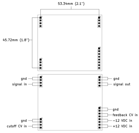
The mechanical format and pinout shared by all plug-in boards:

Signal levels:

  • The plug-in boards are expecting modular synthesizer level signals of around +/- 5 volts.
  • Many filters have interesting resonance and distortion characteristics that depend on signal level. Experiment with increasing and decreasing the signal levels to find the sweet spots.
  • The output signal may or may not be in phase with the input signal.

CV signals:

  • The motherboard is expected to provide a 0 to +2.048 volt cutoff frequency CV signal. The plug-in boards are designed to sweep through their entire range with this range, with 0 volts mapping to the lowest cutoff frequency (usually around 20Hz) and +2.048 volts mapping to the highest cutoff frequency (usually around 20kHz).
  • The feedback CV from the motherboard uses the same range: 0 volts of feedback CV maps to "no feedback" and +2.048 volts of feedback CV maps to maximum feedback.
  • The CV range of 0 to +2.048 volts was chosen becuase it allows the cutoff and feedback CV signals to be conveniently driven directly from a cheap MCP4822 DAC. Don't worry about an exact 2.048 volt range, the filters have trimmers to account for variations.
  • If different scalings are desired it is usually fairly trivial to change some resistor values in the CV scaling circuits on the plug-in boards.

Feedback considerations:

  • The plug-in boards all have voltage controlled feedback. This makes it easier to swap them in and out of a motherboard without worrying about the type and value of feedback potentiometer.
  • This also makes it easier to apply "Q-compensation" to 4-pole low pass filters that suffer from passband attenuation when feedback is increased.
  • All 4-pole filters have some form of Q-compensation built in. The builder can usually adjust the amount of compensation, or choose no compensation at all by changing a single resistor.

Calibration:

  • Each plug-in board has calibration trimpots for modulation depth, center frequency, and feedback sensitivity.
  • For filters that can track at 1 volt per octave, they can probably be trimmed to play in tune over a limited range, but the trimming may be fiddly. Emphasis has been placed on getting a nice sweep through the filters useful range, and not accurate tuning or temperature compensation.
  • Calibration is a matter of taste, and any setup that sounds good to you is correct.
  • Here is how I calibrate Low Pass Filters:
    1. Inject a 30Hz square wave onto the signal input while monitoring the signal output.
    2. Turn the cutoff CV and feedback CV signals all the way down (set them to zero volts).
    3. Adjust the center trim so that the signal just dissapears.
    4. Remove the signal input.
    5. Turn the cutoff CV to around 1/2 way up and turn the feedback CV all the way up.
    6. Adjust the feedback trim until self oscillation occurs.
    7. Turn the cutoff CV signal all the way up.
    8. Adjust the depth trim until the frequency of the self oscillation is around 20kHz.
    9. Sweep the cutoff frequency up and down and readjust the feedback trim as needed to get reliable self oscillation over the desired range. Note that some filters will not self oscillate over their whole frequency range.
    10. Now reinject the signal and listen to the filter while changing the cutoff and feedack CV signals. Readjust the trimmers to taste if desired.
  • I use a similar strategy for other filter topologies like Phase Shifters. Without a self oscillation signal or a strong sense of "cutoff frequency", just adjust the trimmers so that the filter has a nice sweep and the feedback control feels good.
  • The above calibration strategy is very quick and easy once you've done it a few times.

Power supply considerations:

  • The motherboard is expected to provide a +/-12 volt DC power supply.
  • Current draw varies across the filter boards from a handfull of milliamps to a few 10's of milliamps.
  • Ensure that the motherboard can supply at least 100mA or so on each rail.

Starting new plug-in board pcbs:

  • A template is provided to make it easy to start new plug-in board filters.
  • This template contains a standard directory structure, and the start of a kicad project.
  • The template kicad docs have the skeleton of the schematic and pcb.

Project structure:

  • Each filter plug-in board subdirectory follows a consistent structure:
    • kicad_docs/ contains the files needed to open and edit the filter schematic and pcb layout using kicad.
    • construction_docs/ contains a pdf copy of the schematic, an interactive BOM which can be opened in a web browser, and gerbers.
    • pics/ contains a few rendered pics of the pcb.
  • Basically, if you want to edit the filter go into kicad_docs/, if you want to build the filter go into construction_docs/.
  • Note that the filters may be a work in progress and may not contain complete documentation until they are done.
  • See the board status checklist below, any board that is not checked all the way across is likely to contain errors. Boards that are all checked all the way across are safe to build.

Status of the boards:

Boardbreadboardedschematicpcb layoutbuilt and testeddocumentation
2164 phasor☑☑☑☑☑
2164 LPF☑☑☑☑☑
2164 SVF☑☑☑☑☑
arp 4072 LPF☑☑☑☑☑
CEM3320 LPF☑☑☑☑☑
haible 2040 LPF☑☐☐☐☐
haible tau phasor☐☐☐☐☐
Late MS20 VCF☑☑☑☑☑
minimoog LPF☑☑☑☑☑
mutron 3 SVF☑☑☑☑☑
optical phasor☑☑☑☑☑
SSI2140 LPF☑☑☑☑☑

Parts

140
QtyValueFootprintReferences
4015nFCapacitor_SMD:C_0805_2012Metric_Pad1.15x1.40mm_HandSolderC10, C11, C12, C13, C14, C15, C16, C17, C18, C19, C20, C21, C22, C23, C24, C25 +24
22BCM847DS135haible_tau_phaser_plug_in_board:SOT457Q10, Q11, Q12, Q13, Q14, Q15, Q16, Q17, Q18, Q19, Q20, Q21, Q22, Q23, Q24, Q28 +6
9100kResistor_SMD:R_0805_2012Metric_Pad1.15x1.40mm_HandSolderR1, R2, R3, R6, R25, R26, R27, R29, R30
63k3Resistor_SMD:R_0805_2012Metric_Pad1.15x1.40mm_HandSolderR18, R19, R20, R21, R35, R36
418kResistor_SMD:R_0805_2012Metric_Pad1.15x1.40mm_HandSolderR22, R23, R33, R34
4220kResistor_SMD:R_0805_2012Metric_Pad1.15x1.40mm_HandSolderR11, R12, R28, R41
42n2Capacitor_SMD:C_0805_2012Metric_Pad1.15x1.40mm_HandSolderC5, C6, C52, C53
4BC847Package_TO_SOT_SMD:SOT-23_HandsolderingQ2, Q4, Q25, Q26
4TL072Package_SO:SOIC-8_3.9x4.9mm_P1.27mmU1, U3, U4, U5
3220nFCapacitor_SMD:C_0805_2012Metric_Pad1.15x1.40mm_HandSolderC2, C7, C48
322MResistor_SMD:R_0805_2012Metric_Pad1.15x1.40mm_HandSolderR13, R14, R40
333pFCapacitor_SMD:C_0805_2012Metric_Pad1.15x1.40mm_HandSolderC3, C4, C49
3Conn_01x04_MaleConnector_PinHeader_2.54mm:PinHeader_1x04_P2.54mm_VerticalJ1, J2, J3
2100Resistor_SMD:R_0805_2012Metric_Pad1.15x1.40mm_HandSolderR38, R39
21k5Resistor_SMD:R_0805_2012Metric_Pad1.15x1.40mm_HandSolderR42, R43
21uFCapacitor_SMD:C_0805_2012Metric_Pad1.15x1.40mm_HandSolderC50, C51
2220Resistor_SMD:R_0805_2012Metric_Pad1.15x1.40mm_HandSolderR7, R10
230kResistor_SMD:R_0805_2012Metric_Pad1.15x1.40mm_HandSolderR31, R32
23kResistor_SMD:R_0805_2012Metric_Pad1.15x1.40mm_HandSolderR16, R17
247kResistor_SMD:R_0805_2012Metric_Pad1.15x1.40mm_HandSolderR8, R9
250kPotentiometer_SMD:Potentiometer_Bourns_3269W_VerticalRV2, RV3
2BC857Package_TO_SOT_SMD:SOT-23_HandsolderingQ1, Q27
110kPotentiometer_SMD:Potentiometer_Bourns_3269W_VerticalRV1
110nFCapacitor_SMD:C_0805_2012Metric_Pad1.15x1.40mm_HandSolderC54
110pFCapacitor_SMD:C_0805_2012Metric_Pad1.15x1.40mm_HandSolderC1
110uFCapacitor_SMD:C_0805_2012Metric_Pad1.15x1.40mm_HandSolderC55
11n5225BDiode_SMD:D_SOD-123D1
1390Resistor_SMD:R_0805_2012Metric_Pad1.15x1.40mm_HandSolderR15
1470Resistor_SMD:R_0805_2012Metric_Pad1.15x1.40mm_HandSolderR37
1470kResistor_SMD:R_0805_2012Metric_Pad1.15x1.40mm_HandSolderR24
1680kResistor_SMD:R_0805_2012Metric_Pad1.15x1.40mm_HandSolderR5
17k5Resistor_SMD:R_0805_2012Metric_Pad1.15x1.40mm_HandSolderR4
1Conn_01x08_MaleConnector_PinHeader_2.54mm:PinHeader_1x08_P2.54mm_VerticalJ4
1OPA2134Package_SO:SOIC-8_3.9x4.9mm_P1.27mmU2
1wet_polarityJumper:SolderJumper-2_P1.3mm_Open_Pad1.0x1.5mmJP1

More from JordanAceto/VCF_plug_in_boards

12
  • 2 layers58.4 × 50.8 mmHaible 2040 LPF plug in board, the printed circuit board in 3D

    Haible 2040 LPF plug in board

    JordanAceto/VCF_plug_in_boards

    Various small synthesizer Voltage Controlled Filter pcbs

    96 parts11CC-BY-4.0
  • 4 layers58.4 × 50.8 mm2164 phasor plug in board, the printed circuit board in 3D

    2164 phasor plug in board

    JordanAceto/VCF_plug_in_boards

    Various small synthesizer Voltage Controlled Filter pcbs

    92 parts11CC-BY-4.0
  • 2 layers58.4 × 50.8 mmOptical phasor plug in board, the printed circuit board in 3D

    Optical phasor plug in board

    JordanAceto/VCF_plug_in_boards

    Various small synthesizer Voltage Controlled Filter pcbs

    89 parts11CC-BY-4.0
  • 2 layers58.4 × 50.8 mmArp 4072 LPF, the printed circuit board in 3D

    Arp 4072 LPF

    JordanAceto/VCF_plug_in_boards

    Various small synthesizer Voltage Controlled Filter pcbs

    80 parts11CC-BY-4.0
  • 2 layers58.4 × 50.8 mmMinimoog LPF, the printed circuit board in 3D

    Minimoog LPF

    JordanAceto/VCF_plug_in_boards

    Various small synthesizer Voltage Controlled Filter pcbs

    71 parts11CC-BY-4.0
  • 4 layers58.4 × 50.8 mmFour pole lpf, the printed circuit board in 3D

    Four pole lpf

    JordanAceto/VCF_plug_in_boards

    Various small synthesizer Voltage Controlled Filter pcbs

    70 parts11CC-BY-4.0
  • 2 layers58.4 × 50.8 mmLate MS20 VCF plug in board, the printed circuit board in 3D

    Late MS20 VCF plug in board

    JordanAceto/VCF_plug_in_boards

    Various small synthesizer Voltage Controlled Filter pcbs

    66 parts11CC-BY-4.0
  • 2 layers58.4 × 50.8 mmSSI2140 LPF plug in board, the printed circuit board in 3D

    SSI2140 LPF plug in board

    JordanAceto/VCF_plug_in_boards

    Various small synthesizer Voltage Controlled Filter pcbs

    55 parts11CC-BY-4.0
  • 2 layers58.4 × 50.8 mm2164SVF, the printed circuit board in 3D

    2164SVF

    JordanAceto/VCF_plug_in_boards

    Various small synthesizer Voltage Controlled Filter pcbs

    52 parts11CC-BY-4.0
  • 2 layers58.4 × 50.8 mmMutron III plug in board, the printed circuit board in 3D

    Mutron III plug in board

    JordanAceto/VCF_plug_in_boards

    Various small synthesizer Voltage Controlled Filter pcbs

    51 parts11CC-BY-4.0
  • 2 layers58.4 × 50.8 mmCEM3320 LPF plug in board, the printed circuit board in 3D

    CEM3320 LPF plug in board

    JordanAceto/VCF_plug_in_boards

    Various small synthesizer Voltage Controlled Filter pcbs

    42 parts11CC-BY-4.0
  • 2 layers58.4 × 50.8 mmPlug in board template, the printed circuit board in 3D

    Plug in board template

    JordanAceto/VCF_plug_in_boards

    Various small synthesizer Voltage Controlled Filter pcbs

    7 parts11CC-BY-4.0

Similar boards

  • 2 layers89.3 × 50 mmMM58167-ISA RTC, the printed circuit board in 3D

    MM58167-ISA RTC

    jensma-de/MM58167-ISA-RTC

    RTC module for the ISA slot. With schematics, project files in kicad and open source software to drive the clock.

    29 parts9
  • 2 layers254 × 134.1 mmVdm2021, the printed circuit board in 3D

    Vdm2021

    physicsrob/vdm1

    VDM-1 2021 Reproduction

    177 parts1
  • 2 layers200 × 100 mmPolykit x monosynth, the printed circuit board in 3D

    Polykit x monosynth

    polykit/polykit-x-monosynth

    The Polykit X1 is a DIY semi-modular, analog, patchable synthesizer

    167 parts94
  • 2 layers281.1 × 236.5 mmMiniDrumkit2, the printed circuit board in 3D

    MiniDrumkit2

    Fihdi/MiniDrumkit

    Eurorack DrumKit module with a 3 channel wave-file player and analog Hi-Hat and Kick Drum sections

    239 parts15MIT
  • 2 layers19.3 × 106.5 mmKick-808, the printed circuit board in 3D

    Kick-808

    marangisto/Kick-808

    TR-808 Kick Clone

    70 parts8MIT
  • 4 layers190 × 135 mmAudio DSP, the printed circuit board in 3D

    Audio DSP

    HeinVerhallen/Audio-DSP

    545 parts
  • 2 layers60 × 55 mmDualValmorRearBoard, the printed circuit board in 3D

    DualValmorRearBoard

    banjomasterpete/Synth-DIY-Eurorack

    Panels, schematics, boards, etc.

    65 parts12
  • 4 layers118 × 88 mmVinyl adc rev e, the printed circuit board in 3D

    Vinyl adc rev e

    MadsRudolph/vinyl-adc

    Discrete 3rd-order delta-sigma stereo audio ADC, built from op-amps and logic gates: a four-layer Raspberry Pi HAT made by PCBWay, with KiCad files, SPICE simulations and measurements

    184 parts1

Questions

How big is the Haible tau phaser plug in board PCB?

It measures 58.4 × 50.8 mm and has 2 copper layers, 1.6 mm thick.

What parts does the Haible tau phaser plug in board use?

140 parts, built around the TL072, OPA2134UA, BC847 and BC857. The full list of its parts is on this page, with links to each part's symbol and footprint where PCBKit's library has them.

Where can I download the Haible tau phaser plug in board KiCad files?

From the JordanAceto/VCF_plug_in_boards repository on GitHub, at the commit this page was made from: the board is haible_tau_phaser_plug_in_board/kicad_docs/haible_tau_phaser_plug_in_board.kicad_pcb. PCBKit opens the board in the browser, with nothing to install.

Can I use the Haible tau phaser plug in board design in my own project?

Its repository publishes it under the CC-BY-4.0 licence: you may reuse it on that licence's terms (keep the author's notice, and for a copyleft licence share your changes alike).