2 layers111.8 × 161.8 mm

 jcksnvllxr80/usb-controller-321
A USB HID gamepad controller built on the PIC32MX250F128B microcontroller.
Usb controller-32 is an open-source printed circuit board by jcksnvllxr80, from the jcksnvllxr80/usb-controller-32 repository on GitHub. It is a 2-layer board of 194.3 × 109.2 mm with 93 parts on 77 nets, routed with 554 tracks and 5,349 vias.
It is built around the PIC32MX250F128B-I/SS and MAX3232ID. Its parts include 38 resistors, 27 capacitors, 18 switches, 3 ICs and 3 connectors. It belongs with the keyboards and input boards and the PIC boards of this library.


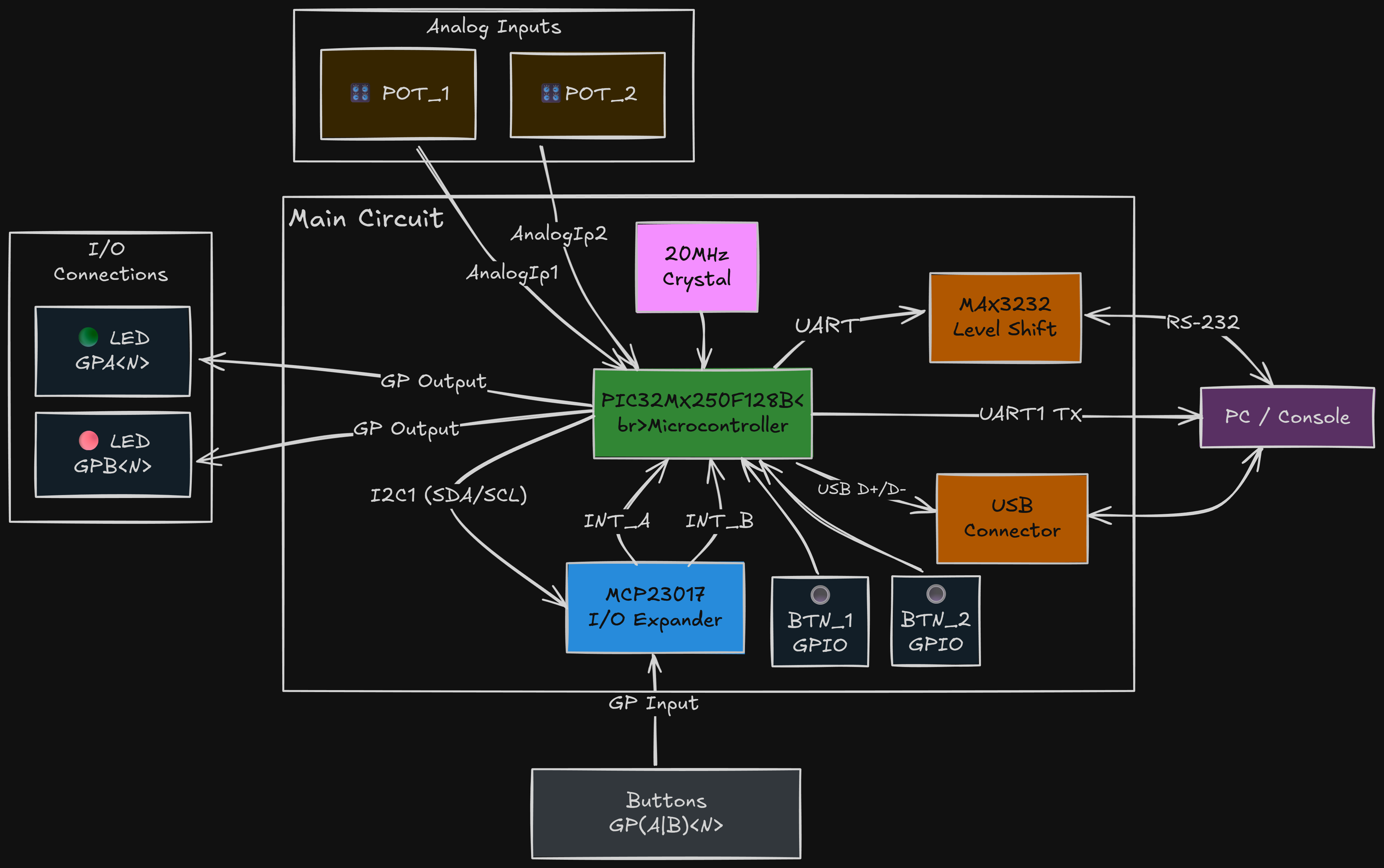
A USB HID gamepad controller built on the PIC32MX250F128B microcontroller. The firmware reads button inputs from GPIO pins, two potentiometers on the PIC32 ADC, and an MCP23017 I2C I/O expander, then reports them to a host PC as a standard USB HID gamepad. The board-level serial path uses a MAX3232 level shifter, and the MCU clock is provided by a 20 MHz crystal. Built with MPLAB Harmony 3, FreeRTOS, and C++.
POT_1 and POT_2 sampled on AN4 / AN5 for Z and RzPOT_1 / POT_2 identificationMain ICs and timing parts on this design:
PIC32MX250F128B - main microcontroller, USB device controller, ADC, GPIO, I2C, and UARTMCP23017 - 16-bit I2C GPIO expander for the additional button inputsMAX3232 - UART level shifter for the board's serial / RS-232 debug path20 MHz crystal - external clock source for the PIC32MX250F128B (load caps C17/C18 must be 20 pF — see Crystal Load Capacitors)2x linear potentiometers - analog controls for POT_1 and POT_2, mapped to HID Z and RzMini USB breakout - USB connector breakout for the device port, such as the small Adafruit mini USB breakout the board is usingC17/C18 must be 20 pF. A 0.1 µF value stops the 20 MHz
crystal from oscillating on the PCB (the board powers up briefly, then drops off USB).
It only appeared to work on the breadboard because the long jumper wires masked the
oversized caps. Full explanation: Crystal Load Capacitors.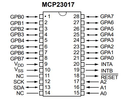
| Signal | Pin | Port | Direction | Description |
|---|---|---|---|---|
| MCLR | 1 | — | Input | Master clear (active-low reset); 10k pull-up to VDD; PICkit 5 pin 1 (VPP) |
| PGED1 | 2 | RA0 | Programming | ICSP data (PICkit 5 pin 4) |
| PGEC1 | 3 | RA1 | Programming | ICSP clock (PICkit 5 pin 5) |
| GREEN_LED | 4 | RB0 | Output | Green status LED |
| RED_LED | 5 | RB1 | Output | Red status LED |
| POT_1 | 6 | RB2 / AN4 | Input | Analog potentiometer mapped to HID Z axis |
| POT_2 | 7 | RB3 / AN5 | Input | Analog potentiometer mapped to HID Rz axis |
| VSS | 8 | — | Power | Ground |
| OSC1 | 9 | RA2 | Input | 20 MHz crystal input |
| OSC2 | 10 | RA3 | Output | 20 MHz crystal output |
| U1TX | 11 | RB4 | Output | UART1 transmit (debug) |
| U1RX | 12 | RA4 | Input | UART1 receive (debug) |
| VDD | 13 | — | Power | 5V supply |
| INTERRUPT_A | 14 | RB5 | Input | MCP23017 Port A interrupt (active-low) |
| VBUS | 15 | — | Power | USB 5V bus voltage; connected to VCC |
| INTERRUPT_B | 16 | RB7 | Input | MCP23017 Port B interrupt (active-low) |
| SCL1 | 17 | RB8 | Output | I2C1 clock to MCP23017 |
| SDA1 | 18 | RB9 | Bidirectional | I2C1 data to MCP23017 |
| VSS | 19 | — | Power | Ground |
| VCAP | 20 | — | Power | Internal core regulator output; 0.1µF cap to VSS |
| D+ | 21 | — | Bidirectional | USB data plus |
| D− | 22 | — | Bidirectional | USB data minus |
| VUSB3V3 | 23 | — | Power | USB 3.3V supply; decoupling capacitors to GND |
| RB13 | 24 | RB13 | NC | Not connected |
| BUTTON_1 | 25 | RB14 | Input | Direct button input 1 |
| BUTTON_2 | 26 | RB15 | Input | Direct button input 2 |
| AVSS | 27 | — | Power | Analog ground |
| AVDD | 28 | — | Power | 5V analog supply |
| Port | Pins | Direction | Pull-ups | Interrupt | Description |
|---|---|---|---|---|---|
| Port A | GPA0–GPA7 | Input | Enabled | Enabled (interrupt-on-change) | 8 button inputs |
| Port B | GPB0–GPB7 | Input | Enabled | Enabled (interrupt-on-change) | 8 button inputs |
| Type | Count | Source | Details |
|---|---|---|---|
| Button inputs (direct) | 2 | PIC32 GPIO | RB14, RB15 |
| Button inputs (expanded) | 16 | MCP23017 Port A & B | GPA0–7, GPB0–7 |
| Analog inputs | 2 | PIC32 ADC | POT_1 on AN4 drives HID Z, POT_2 on AN5 drives HID Rz |
| LED outputs | 2 | PIC32 GPIO | Green (RB0), Red (RB1) |
| USB HID | 1 | USB peripheral | 18 buttons, hat switch, X/Y centered, live Z/Rz in an 8-byte report |
| Debug UART | 1 | UART1 via MAX3232 | 115200 baud debug/serial path (TX: RB4, RX: RA4) |
| I2C bus | 1 | I2C1 | MCP23017 at 0x20 |
Ctrl+Shift+X).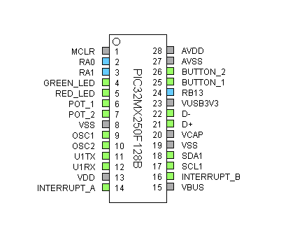
git clone https://github.com/jcksnvllxr80/usb-controller-32.git
cd usb-controller-32cmake/ directory.Ctrl+Shift+B)..hex file to the PIC32MX250F128B.Warning: Use a native USB 2.0 port when connecting this controller to the PC. On some machines, USB 3.x ports/controllers can fail enumeration or produce a Windows Code 10 error with this hardware. If your machine does not have a USB 2.0 port, connect the controller through a USB 2.0 hub.
Z / Rz potentiometer movement are registered.Helper scripts:
powershell -ExecutionPolicy Bypass -File .\tools\uart_query.ps1powershell -ExecutionPolicy Bypass -File .\tools\uart_cmd.ps1 -cmd "status"Useful commands:
status - GPIO, USB, and LED summaryusb - USB device state and register dumpenum - enumeration counters and last setup requesthid - HID readiness, send counters, and current report bytesusblog - recent USB transaction logusbdbg - toggle live USB debug loggingusbreset - soft detach/reattach to force re-enumerationAutomatic serial logs:
[POT] POT_1 axis=... and/or [POT] POT_2 axis=...APP_Tasks().POT_1 and POT_2 are polled in APP_Tasks(), scaled from 10-bit ADC samples to 8-bit HID axis values, and mapped to HID Z and Rz.Z / Rz byte changes.POT_1, POT_2, or both), skip repeated values, and are rate-limited to 5 lines per second.usb-controller-32/
├── cmake/ # CMake build configurations
├── docs/ # Datasheets, block diagram, images
├── tools/ # Flash and UART helper scripts
├── usb-controller-32/
│ ├── mcc/ # MPLAB Code Configurator files
│ └── src/
│ ├── main.cpp # Entry point (SYS_Initialize + SYS_Tasks)
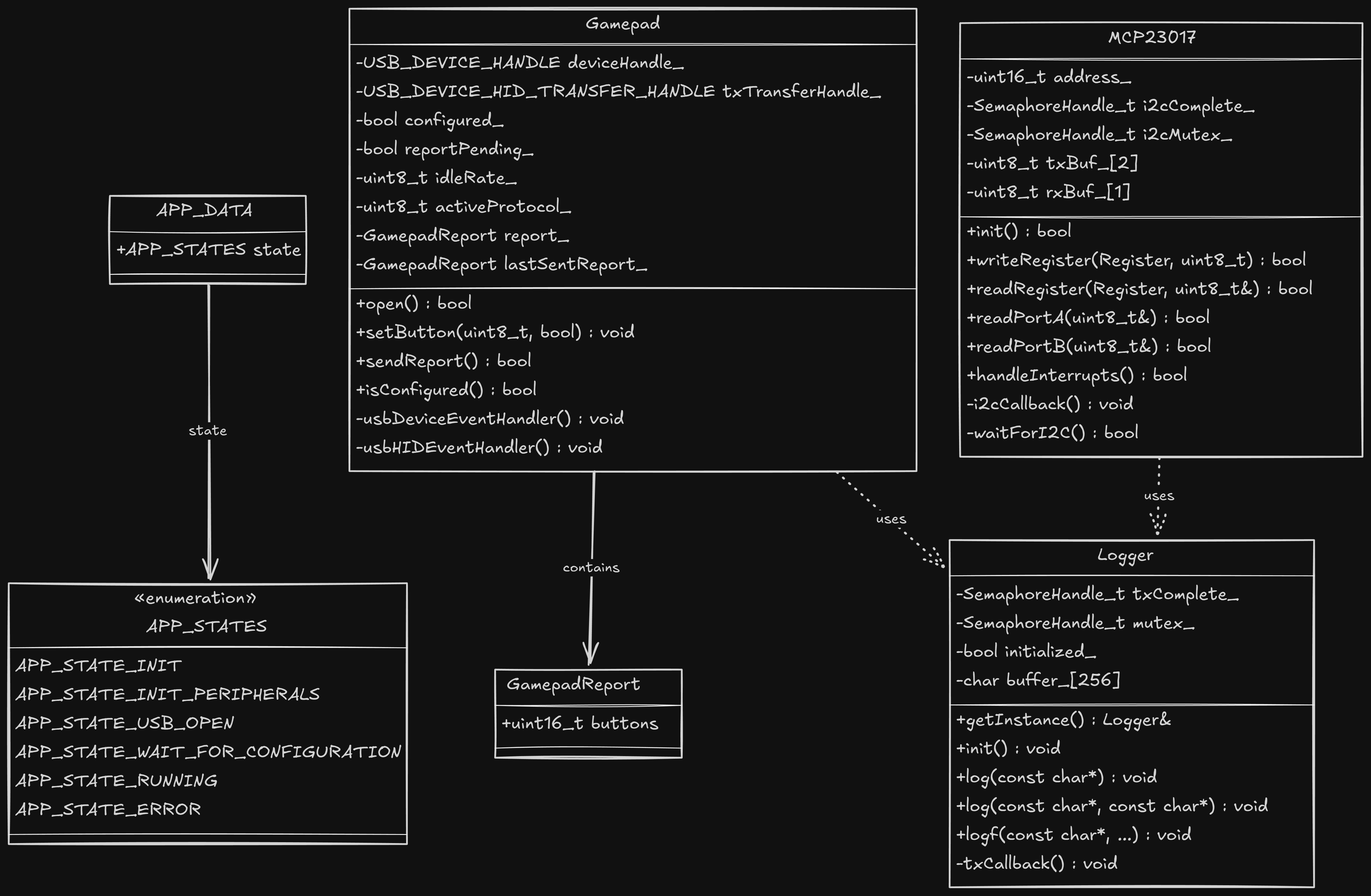
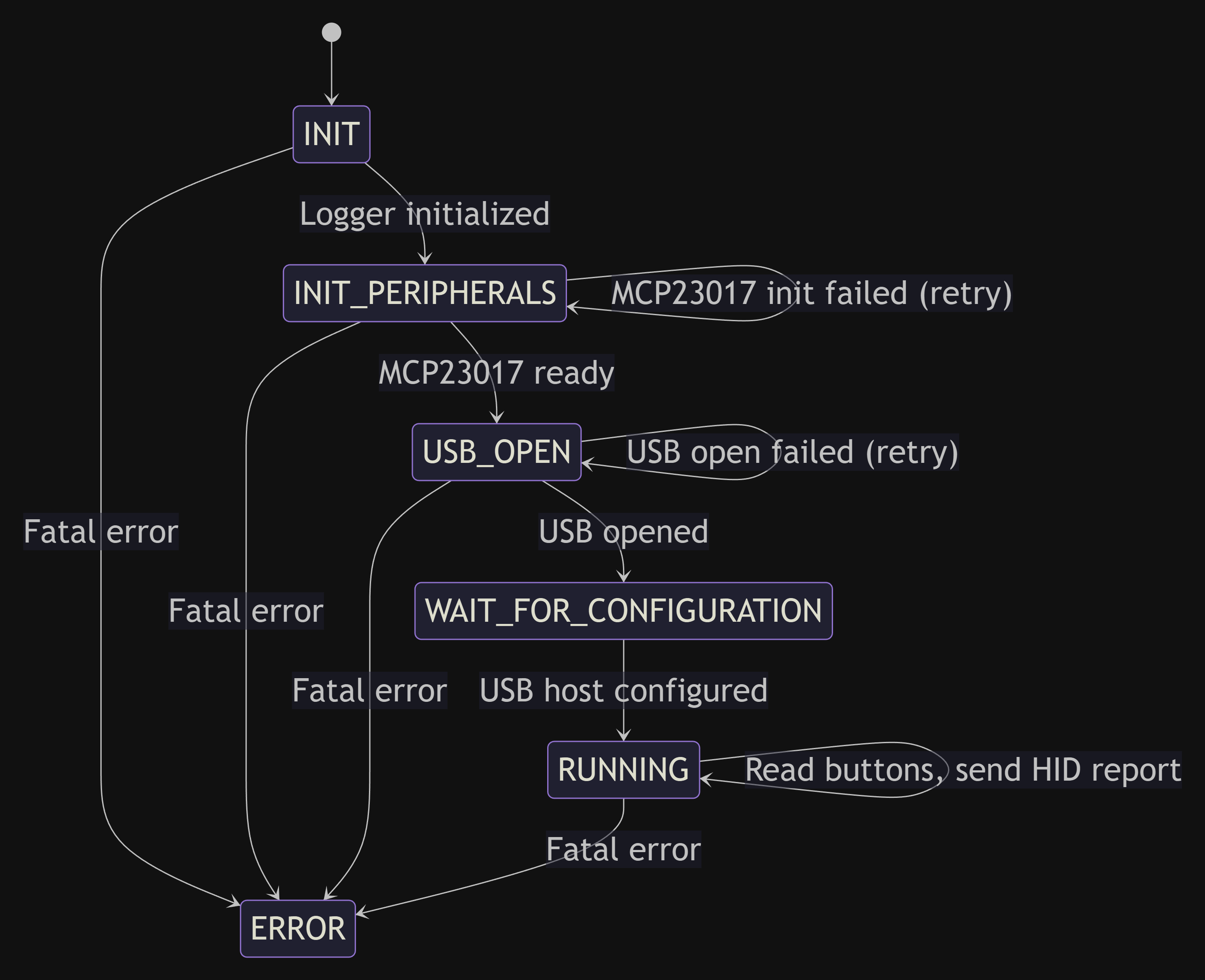
│ ├── app.cpp / app.h # App task, GPIO/MCP state, USB HID send path
│ ├── command_handler.cpp / .h # UART command parser and diagnostics
│ ├── gamepad.cpp / .h # USB HID gamepad driver
│ ├── mcp23017.cpp / .h # MCP23017 I2C I/O expander driver
│ ├── logger.cpp / .h # UART debug logger (singleton)
│ ├── usb_debug.c / .h # USB debug logging helpers
│ ├── config/ # Harmony-generated peripheral config
│ └── third_party/rtos/ # FreeRTOS source
└── README.mdPCB prototyping for this project is sponsored by PCBWay.
PCBWay makes it easy to go from design files to manufactured boards. Upload your Gerber files, pick your board specs (layers, thickness, surface finish, color, etc.), and get an instant quote. Orders typically ship within a few days. Their online ordering process is straightforward — just create an account, upload your files, review the specs, and check out.
See Microchip's license terms in the source file headers.
| Qty | Value | Footprint | References |
|---|---|---|---|
| 32 | 12k | Resistor_THT:R_Axial_DIN0207_L6.3mm_D2.5mm_P10.16mm_Horizontal | R1, R2, R10, R11, R12, R13, R14, R15, R16, R17, R18, R19, R20, R21, R22, R23 +16 |
| 25 | 0.1µF | Capacitor_THT:C_Disc_D5.0mm_W2.5mm_P2.50mm | C1, C2, C10, C11, C12, C13, C14, C15, C16, C17, C18, C19, C20, C21, C24, C25 +9 |
| 18 | SW_Push_Dual | Button_Switch_THT:SW_TH_Tactile_Omron_B3F-100x | SW1, SW2, SW3, SW4, SW5, SW6, SW7, SW10, SW11, SW12, SW13, SW14, SW15, SW16, SW17, SW18 +2 |
| 2 | 0.01µF | Capacitor_THT:C_Disc_D5.0mm_W2.5mm_P2.50mm | C22, C23 |
| 2 | 4.7k | Resistor_THT:R_Axial_DIN0207_L6.3mm_D2.5mm_P10.16mm_Horizontal | R36, R37 |
| 2 | R_Potentiometer | Potentiometer_THT:Potentiometer_Bourns_3386P_Vertical | RV1, RV2 |
| 1 | 1.2k | Resistor_THT:R_Axial_DIN0207_L6.3mm_D2.5mm_P10.16mm_Horizontal | R34 |
| 1 | 10k | Resistor_THT:R_Axial_DIN0207_L6.3mm_D2.5mm_P10.16mm_Horizontal | R35 |
| 1 | 15k | Resistor_THT:R_Axial_DIN0207_L6.3mm_D2.5mm_P10.16mm_Horizontal | R38 |
| 1 | 20MHz | Crystal:Crystal_HC49-4H_Vertical | Y1 |
| 1 | 8.2k | Resistor_THT:R_Axial_DIN0207_L6.3mm_D2.5mm_P10.16mm_Horizontal | R33 |
| 1 | Conn_01x03_Pin | Connector_PinHeader_2.54mm:PinHeader_1x03_P2.54mm_Vertical | J3 |
| 1 | Conn_01x08_Pin | Connector_PinHeader_2.54mm:PinHeader_1x08_P2.54mm_Vertical | J2 |
| 1 | LED_Dual_AKA | LED_THT:LED_D3.0mm-3 | D2 |
| 1 | MAX3232 | Package_DIP:DIP-16_W7.62mm | U2 |
| 1 | MCP23017x-x-SP | Package_DIP:DIP-28_W7.62mm | U3 |
| 1 | PIC32MX250F128B | Package_DIP:DIP-28_W7.62mm | U1 |
| 1 | USB_MiniB_Adafruit_Breakout | extra:USB_MiniB_Adafruit_Breakout | J1 |

PinguinoIDE/pinguino-cad
Open Hardware Pinguino boards (and extensions) CAD files (Kicad)

davischris/OpenAC1
This work is largely based on the work of Tor-Eirik Bakke Lunde (https://github.com/tebl/RC6502-Apple-1-Replica).

biomurph/ILV2-7-5_VFD_Display
KiCAD circuit for a VFD Clock using the Popular ILV2-7/5 flat tube segmented nixie

BostonUniversitySeniorDesign/brain-4ce
Where thoughts become motion. Designed by BU ECE 2023 Senior Design Capstone Team 4 From left to right: Brendan Shortall, Mitchell Gilmore, Dayanna De La Torres, Jonathan Mikalov, Alexander Johnson


doudar/SmartSpin2k
Transform your spin bike into a Smart Trainer!
It measures 194.3 × 109.2 mm and has 2 copper layers, 1.6 mm thick.
93 parts, built around the PIC32MX250F128B-I/SS and MAX3232ID. The full list of its parts is on this page, with links to each part's symbol and footprint where PCBKit's library has them.
From the jcksnvllxr80/usb-controller-32 repository on GitHub, at the commit this page was made from: the board is pcb/usb-controller-32/usb-controller-32.kicad_pcb and its schematic pcb/usb-controller-32/usb-controller-32.kicad_sch. PCBKit opens the board in the browser, with nothing to install.
Its repository states no licence, so its author keeps all rights: ask jcksnvllxr80 before reusing the design.