2 layers45 × 39 mm

 biomurph/ILV2-7-5_VFD_Display3
KiCAD circuit for a VFD Clock using the Popular ILV2-7/5 flat tube segmented nixie
ILV2-7-5 Clock is an open-source printed circuit board by biomurph, from the biomurph/ILV2-7-5_VFD_Display repository on GitHub, published under the GPL-3.0 licence. It is a 2-layer board of 92 × 76 mm with 50 parts on 61 nets, routed with 329 tracks and 36 vias.
It is built around the PIC32MX250F128B-I/SS, MAX6920AWP+ and 74HC2G14GW, with the DS3231MZ+, TC1014-2.5VCT713 and TLV76033DBZR among its other parts. Its parts include 17 capacitors, 10 resistors, 6 ICs, 4 transistors and 4 switches. It belongs with the lEDs and displays boards and the PIC boards of this library.


KiCAD circuit for a VFD Clock using the Popular ILV2-7/5 flat tube segmented nixie tube thingie
Not sure if this link still works
This work is greatly indebted to work that came before. Namely Callum Nunez-Vas and his Dogbone Watch which is also based on the cyberpunk wristwatch by johngineer.
I made some changes.
First, my uC is a PIC32MX250F128B, which supports USB OTG, which is nice and it's also Arduino compatible via ChipKIT and Digilent's DP32 which makes it nice for sharing.
The other thing that I changed is the oscillator that Callum used to drive the Cathode filament. Callum drives it with a timer on his PIC16F828. I needed more pins, so I decided to make a stand-alone relaxation oscillator built out of a 74HCG214 dual Schmidtt Trigger Inverter. I set mine up as a dual oscillator clocking at ~1KHz to drive the hours/mimutes Cathodes.
There's two pushbuttons for interfacing and an LED for control and user feedback. I'm using the same DS3231 that Callum uses, and also the MAX6920 for the high voltage SIPO to drive the segments.
It's pretty basic beyond that. The power supply is based on the Dogbone, but I'm using a 3V0 regulator instead of a 3V3 and I have a V-divider set up as a battery level sensor that the PIC can read.
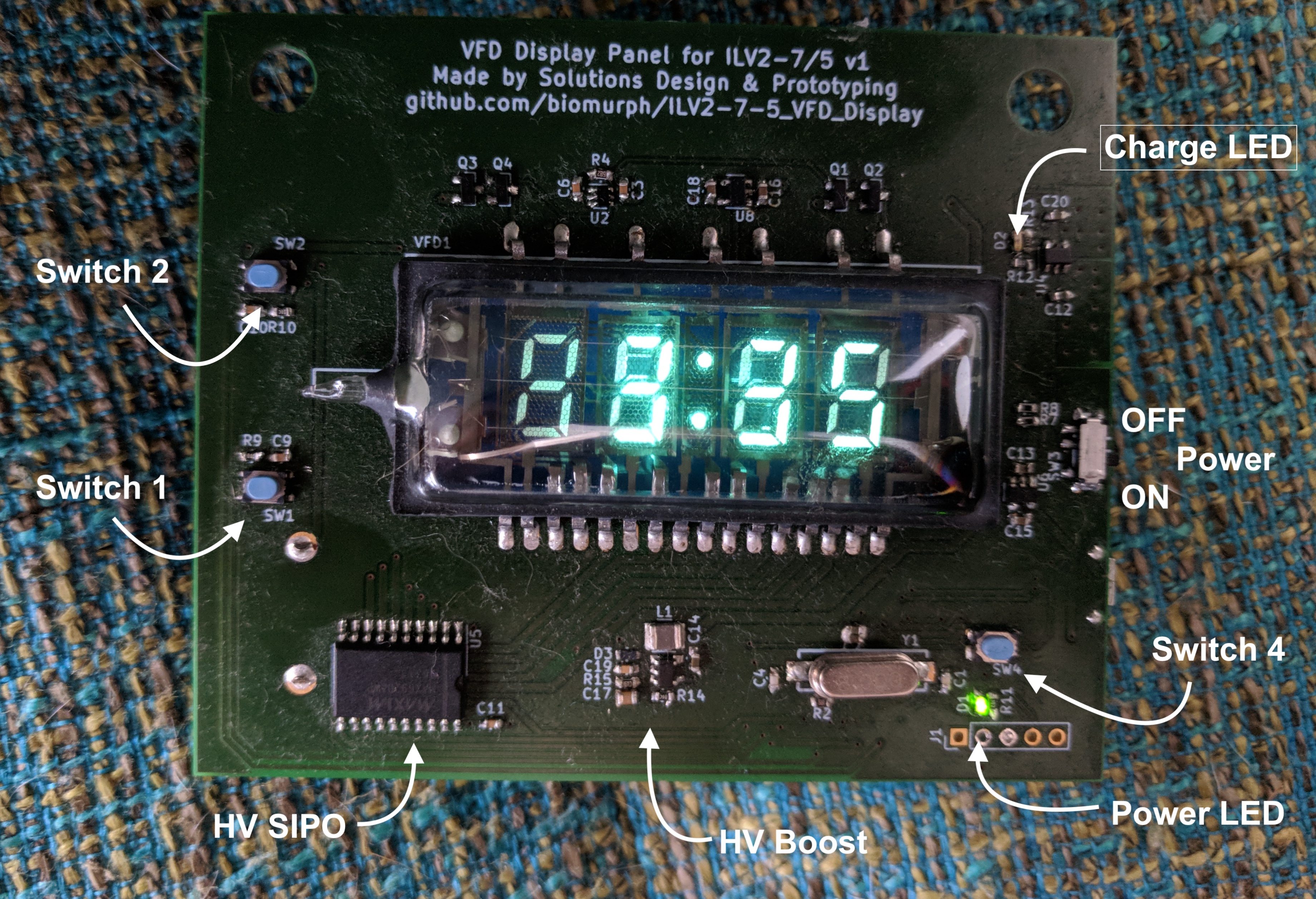
Press Switch 2 once. The screen will print a lowercase b and then the voltage level with 0.01mV resolution. Press again to go back to time display.
Press Switch 1 once. Hour will blink. Press Switch 2 to increment hour.
Press Switch 1 again. Minute will blink. Press Switch 2 to increment minute.
Press Switch 1 again. Display will show option between 24 hour and 12 hour time. Press Switch 2 to toggle between 24h and 12h.
Press Switch 1 again to go back to the time display.
Switch 4 is the reset switch to the PIC. When you press it, the micro-contoller resets. It will start in 24 hour mode.
The thing runs on a high capacity LiPo battery. Plug it into a micro USB cable for charging. You can also program the PIC through the USB connection if you want to.
| Qty | Value | Footprint | References |
|---|---|---|---|
| 6 | 0.1uF | Capacitors_SMD:C_0603 | C3, C5, C8, C9, C10, C11 |
| 6 | 10k | Capacitors_SMD:C_0603 | R1, R4, R5, R6, R9, R10 |
| 6 | 1uF | Capacitors_SMD:C_0603 | C2, C13, C15, C16, C18, C21 |
| 3 | TACT_SWITCH | Solutions:D6_SPST_SW | SW1, SW2, SW4 |
| 2 | 18pF | Capacitors_SMD:C_0603 | C1, C4 |
| 2 | 22R | Capacitors_SMD:C_0603 | R7, R8 |
| 2 | 500mA 30V | Capacitors_SMD:C_0603 | D2, D3 |
| 2 | BSS138 | TO_SOT_Packages_SMD:SOT-23 | Q2, Q4 |
| 2 | BSS84 | TO_SOT_Packages_SMD:SOT-23 | Q1, Q3 |
| 1 | 0.15uF | Capacitors_SMD:C_0603 | C6 |
| 1 | 10K | Capacitors_SMD:C_0603 | R3 |
| 1 | 10uF | Capacitors_SMD:C_0603 | C7 |
| 1 | 1k | Capacitors_SMD:C_0603 | R11 |
| 1 | 4.7uF 50V | Capacitors_THT:CP_Radial_D5.0mm_P2.00mm | C17 |
| 1 | 74HC2G14 | TO_SOT_Packages_SMD:SOT-363_SC-70-6 | U2 |
| 1 | 8MHz | Solutions:TXC_5mmX2mm | Y1 |
| 1 | BARREL_JACK | Solutions:DC_PWR_PJ-006B | J3 |
| 1 | Battery_Cell | Solutions:12BH062-GR | BT1 |
| 1 | CONN_01X05 | Pin_Headers:Pin_Header_Straight_1x05_Pitch2.54mm | J1 |
| 1 | DS3231M | SMD_Packages:SOIC-8-N | U1 |
| 1 | GF-1123-1110 | Solutions:SW_GF-1123-1110 | SW3 |
| 1 | ILV2-7/5 | Solutions:IVL2-7-5 | VFD1 |
| 1 | LED | Capacitors_SMD:C_0603 | D1 |
| 1 | MAX6920 | Housings_SOIC:SO-20_12.8x7.5mm_Pitch1.27mm | U5 |
| 1 | PIC32MX250F128B | SMD_Packages:SOIC-28 | U3 |
| 1 | TC1014-2.5VCT713 | TO_SOT_Packages_SMD:SOT-23-5 | U8 |
| 1 | TLV76033DBZR | TO_SOT_Packages_SMD:SOT-23 | U4 |
| 1 | USB_OTG | Solutions:10118193_microUSB | J2 |


PinguinoIDE/pinguino-cad
Open Hardware Pinguino boards (and extensions) CAD files (Kicad)

davischris/OpenAC1
This work is largely based on the work of Tor-Eirik Bakke Lunde (https://github.com/tebl/RC6502-Apple-1-Replica).

BostonUniversitySeniorDesign/brain-4ce
Where thoughts become motion. Designed by BU ECE 2023 Senior Design Capstone Team 4 From left to right: Brendan Shortall, Mitchell Gilmore, Dayanna De La Torres, Jonathan Mikalov, Alexander Johnson

jcksnvllxr80/usb-controller-32
A USB HID gamepad controller built on the PIC32MX250F128B microcontroller.

It measures 92 × 76 mm and has 2 copper layers, 1.6 mm thick.
50 parts, built around the PIC32MX250F128B-I/SS, MAX6920AWP+, 74HC2G14GW and DS3231MZ+. The full list of its parts is on this page, with links to each part's symbol and footprint where PCBKit's library has them.
From the biomurph/ILV2-7-5_VFD_Display repository on GitHub, at the commit this page was made from: the board is ILV2-7-5_Clock/ILV2-7-5_Clock.kicad_pcb. PCBKit opens the board in the browser, with nothing to install.
Its repository publishes it under the GPL-3.0 licence: you may reuse it on that licence's terms (keep the author's notice, and for a copyleft licence share your changes alike).