2 layers245.2 × 100 mm
V5 main
zynthian/zynthian-hw
Zynthian hardware stuff: PCBs, schemes, parts specifications, pin assignment, ...
160 parts156
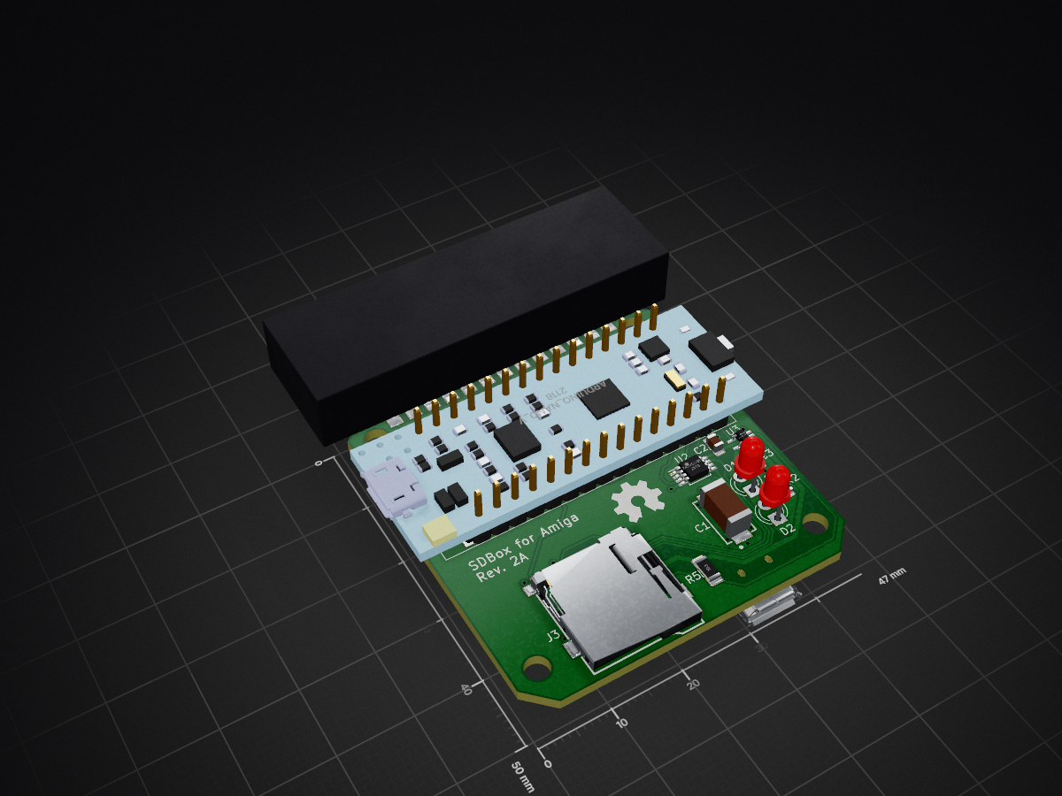
 jbilander/SDBox-v253
SDBox-v2 for Amiga, compatible with the new updated card-detect firmware
SDBox is an open-source printed circuit board by jbilander, from the jbilander/SDBox-v2 repository on GitHub, published under the GPL-3.0 licence. It is a 2-layer board of 47 × 50 mm with 22 parts on 48 nets, routed with 203 tracks and 28 vias.
It is built around the 74LVC1G17Z, 74LVC3G17DP and T491D227K010AT. Its parts include 7 resistors, 4 capacitors, 3 ICs, 3 connectors and 2 diodes. It belongs with the AVR (ATmega, ATtiny) boards of this library.


SDBox v2 for Amiga, hardware compatible with the new updated card-detect (insert/eject interrupt) firmware written by N.Ekström available here: https://github.com/niklasekstrom/amiga-par-to-spi-adapter
This version is superseded by the new SDBox-v3 here: https://github.com/jbilander/SDBox-v3


Here is a short video clip showing the new card detect feature:
https://drive.google.com/file/d/11R0idJcfvWwsGSfzbPFG1xpoupvCA6SC/view?usp=sharing

Start by soldering the U2 and U3 ICs, then the passives, the card holder, micro-usb jack, DB25M and so on, nothing complicated, but do skip the 6-pin ICSP-header on the Nano if you're going to put this in a 3D-printed case...


At this stage, before you solder the Nano down to the board, you should verify that +5V via the Micro-USB jack is ok...


Now the Nano, validate +5V and +3.3V is ok on the Nano:
Powering the MicroSD card directly from the 3.3V-pin of the Arduino, are you nuts?
Well, maybe, but typical SD card current consumption is ~30mA in SPI mode.
The Arduino Nano taps 3.3V from the internal LDO 3V3OUT supply of the FT232RL USB-chip, or in case of the clones the CH340 USB-chip.
FT232RL: Up to 50mA can be drawn from this pin to power external logic if required.
CH340G: Maximum output current is 30mA, and that voltage stays rather stable up to about 30mA.


Time to build and flash the firmware:


And we need to 3D-print a case for it before we put the LEDs in, don't we?...
(STL-files available in the DSM folder)


Final result:


Comparison with v1, look at the difference in size:


Now time to build the new spisd.device driver, add +kick13 to the build.bat if default is set to build for AmigaOS 2.0...
(VBCC for Windows I downloaded from here (Thanks: Leffmann for the installer), https://eab.abime.net/showthread.php?t=83113 )


| Position | Name/Value | Package | Notes |
|---|---|---|---|
| U1 | Arduino Nano V3 | ||
| U2 | 74LVC3G17 | TSSOP-8_3x3mm_P0.65mm | Triple non-inverting Schmitt trigger with 5V tolerant input 74LVC3G17 |
| U3 | 74AHCT1G17 | 5-TSSOP, SC-70-5, SOT-353 (2.0 mm × 1.25mm) | Single non-inverting Schmitt trigger 74AHCT1G17GWH |
| J1 | D-Sub DB25M | DB25 Male connector with solder lugs | DB25 for Amiga parallel port |
| J2 | Micro USB connector | USB Micro B SMT | For +5V Power, (style 1) https://www.aliexpress.com/item/32991869539.html |
| J3 | Micro SD Card Holder | 9-pin Micro SD card slot connector | https://www.aliexpress.com/item/32802051702.html |
| D1 (Optional) | LED 3mm | PinHeader_1x02_P2.54mm_Vertical, pin pitch 2.54 mm | SD Activity LED indicator, Diffused Orange / Amber, 1.8V-2.3V, 20-30 mA, 605-610nm |
| D2 (Optional) | LED 3mm | PinHeader_1x02_P2.54mm_Vertical, pin pitch 2.54 mm | Power LED indicator, Green Diffused T-1, 25 mcd, 565 nm, 2.2 V, 25 mA |
| R1 (Optional) | 150 Ohm Resistor | 1206 SMD, 200 mW | (Mandatory if D1 populated) Series resistor for D1 LED, adjust R-value to your type of LED and preferred brightness |
| R2 (Optional) | 150 Ohm Resistor | 1206 SMD, 200 mW | (Mandatory if D2 populated) Series resistor for D2 LED, adjust R-value to your type of LED and preferred brightness |
| R3 | 10k Ohm Resistor | 1206 SMD | Pull-up (to VCC) resistor for /SS |
| R4 (Optional) | 10k Ohm Resistor | 1206 SMD | Pull-up (to VCC) resistor for MOSI |
| R5 | 10k Ohm Resistor | 1206 SMD | Pull-up (to 3V3) for MISO_3V3 |
| R6 | 10k Ohm Resistor | 1206 SMD | Pull-up (to 3V3) for DAT1 pin 8 on MicroSD-holder |
| R7 | 10k Ohm Resistor | 1206 SMD | Pull-up (to 3V3) for DAT2 pin 1 on MicroSD-holder |
| JP1 (Optional) | 0 Ohm Resistor, or Solder Blob | 1206 SMD | Populate this one to reset Nano in conjunction with Ctrl-Amiga-Amiga |
| C1 | 220uF Capacitor | SMD-Tantalum, 4.3 x 7.3 x 2.8 mm | Capacitor for VIN +5V Power via USB https://www.reichelt.com/se/en/smd-tantalum-220-f-10v-125-c-t491d-220u-10-p206492.html |
| C2 | 0.1uF = 100nF Capacitor | 0805 SMD | Decoupling capacitor for U2 |
| C3 | 0.1uF = 100nF Capacitor | 0805 SMD | Decoupling capacitor for U3 |
| C4 | 0.1uF = 100nF Capacitor | 0805 SMD | Decoupling capacitor for J3 |


I did't have a DB23 Male connector so I used a DB25 and cut it down to a 23 with a hacksaw. I cut on the left side (pin 1 and 14) so that the plug will clear the neighbouring RCA-jack when plugged into the A500 external floppy drive port.


Remove pin 1 and 14, wiggle back and forth with a plier until they exhaust and snap then pull out the remains from the other side


Cut and wirestrip the micro-usb cable. Verify polarity, normally black is GND and red is +5V but the cable mfg might have mixed up the wire colours so check with a multimeter to be certain. Pin 3-7 on the connector is GND on the Amiga, +5V is on pin 12. You could either Blob pin 3-7 together (requires quite a lot of solder) and then solder the micro-usb GND-wire to that Blob or do as I did below with 5 individual wires soldered and crimped together.


Some shrink tube on, a bit overkill maybe but hey it's a guide, no shortcuts, I even crimped AND soldered the GND-joint :)


Ready to go and it clears both the RCA-plug and the serial port connector. With this cable now plugged into the SDBox it'll be powered on as soon as the Amiga is powered on and vice versa.

Happy Hackin'
| Qty | Value | Footprint | References |
|---|---|---|---|
| 5 | 10k | Resistor_SMD:R_1206_3216Metric_Pad1.42x1.75mm_HandSolder | R3, R4, R5, R6, R7 |
| 3 | 0.1uF | Capacitor_SMD:C_0805_2012Metric_Pad1.15x1.40mm_HandSolder | C2, C3, C4 |
| 2 | 150 | Resistor_SMD:R_1206_3216Metric_Pad1.42x1.75mm_HandSolder | R1, R2 |
| 1 | 74LVC1G17 | SDBox:SOT-353_SC-70-5_Custom_Handsoldering | U3 |
| 1 | 74LVC3G17 | SDBox:TSSOP-8_3x3mm_P0.65mm_Custom_Handsoldering | U2 |
| 1 | Activity LED indicator | LED_THT:LED_D3.0mm | D1 |
| 1 | Arduino_Nano_V3 | SDBox:Arduino_Nano_V3 | U1 |
| 1 | DB25_Male | Connector_Dsub:DSUB-25_Male_EdgeMount_P2.77mm | J1 |
| 1 | Jumper_2_Open | Resistor_SMD:R_1206_3216Metric_Pad1.42x1.75mm_HandSolder | JP1 |
| 1 | Micro_SD_Card_Socket | SDBox:GCT-MEM2055-00-190-01-A | J3 |
| 1 | Power LED indicator | LED_THT:LED_D3.0mm | D2 |
| 1 | T491D227K010AT | SDBox:CAPMP7343X430N | C1 |
| 1 | USB_B_Micro | SDBox:USB_Micro-B_Unknown_5s_SMT | J2 |
The 20 most common of 22 parts.
It measures 47 × 50 mm and has 2 copper layers, 1.6 mm thick.
22 parts, built around the 74LVC1G17Z, 74LVC3G17DP and T491D227K010AT. The full list of its parts is on this page, with links to each part's symbol and footprint where PCBKit's library has them.
From the jbilander/SDBox-v2 repository on GitHub, at the commit this page was made from: the board is KiCad/SDBox.kicad_pcb. PCBKit opens the board in the browser, with nothing to install.
Its repository publishes it under the GPL-3.0 licence: you may reuse it on that licence's terms (keep the author's notice, and for a copyleft licence share your changes alike).
zynthian/zynthian-hw
Zynthian hardware stuff: PCBs, schemes, parts specifications, pin assignment, ...

anthony-bernaert/ftdi-jtag-programmer
FTDI-based JTAG Programmer Circuit for FPGAs


jbilander/SDBox-Mini
SDBox Mini for Amiga, compatible with the new updated card-detect firmware


pollen-robotics/elec_Poulpe_3d
Tripple Motor Control Board for Reachy 2

calperxd/tangnano9k-kr260-hat
FPGA HAT for the AMD Kria KR260 based on the Tang Nano 9K (Gowin GW1NR-9, FT2232H, 16-bit parallel link on J21): KiCad 10 schematic, 4-layer PCB and JLCPCB production files