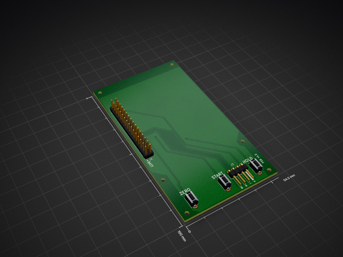
PendantPcb is an open-source printed circuit board by Jay-Tech, from the Jay-Tech/WirelessPendant repository on GitHub. It is a 2-layer board of 54.5 × 100 mm with 11 parts on 31 nets, routed with 34 tracks and 2 vias.
Its parts include 3 switches and 2 connectors.
README
README.md
Wireless Pendant
Firmware for a wireless handwheel pendant for a grblHAL machine, and for the
receiver board that carries it to the PC. The sender application it talks to is
a separate project — Jay-Tech/GrblHAL-Sender,
whose Wireless Pendant
section covers the settings at that end. What crosses between them is
the wire protocol — newline-delimited JSON,
the same either way it travels.
Two boards, both ESP32-S3:
pendant
the handheld — encoder wheel, touch screen, battery. Waveshare ESP32-S3-Touch-LCD-3.5
receiver
plugs into the sender's PC, presents a serial port, talks ESP-NOW to the pendant
The pendant reaches the sender two ways. Over ESP-NOW it talks to the
receiver board, which needs no network and no credentials — this is the one it
is built around, because an open-source pendant cannot require the builder to
have usable WiFi in their shop. Over WiFi it joins the shop network and
opens a TCP session to the sender directly; that path stays because it is the
reference every jog constant was fitted against.
Three things, and none of them is a breadboard any more: an all-in-one host
board, a passive PCB that breaks its header out, and a printed enclosure. All of
it lives under hardware/.
Fusion 360 sources and printable STLs — the handheld, and a dock for it
The bill of materials is five orderable items, with no passives at all: the
host board, an MPG handwheel, three tactile switches, a LiPo cell, and whatever
the printer eats. A 5 V boost module and the encoder's 22 kΩ divider pair were
both on that list until 2026-08-15 and were measured off it rather than reasoned
off it — platform-decision.md carries the
numbers, and Encoder wiring below keeps the divider material
for the Pico build and for characterising an unknown wheel.
one 32-pin, 2.54 mm header — which is what PSB v1.0 mates to
Two of those are why the board won. The IPEX connector — reached by
resoldering one resistor — is worth more on a handheld carried around a steel
machine than any latency figure measured here, and the Pico 2 W's antenna is
fixed. The AXP2101 does in one part what the Pico build needed a LiPo Amigo
Pro and its wiring to do. The 8 MB PSRAM is enough for a full 320x480x2
framebuffer, which is also why the committed MicroPython build is the
SPIRAM_OCT variant rather than the plain one — see ESP32-S3.
The pin map is not in Waveshare's wiki and cannot be read off their schematic
PDF. It came from their demo code, examples 08 and 11, which agree — and three
of the pins turn out not to be pins:
The LCD has no chip select. The panel is permanently selected, so
st7796.py has to tolerate cs=None rather than toggle something that does
not exist.
LCD reset is an I²C write, to a TCA9554 expander at 0x20 that is not
in the board's advertised feature list and answers writes but not reads. The
driver takes a reset callable instead of a pin, so the caller supplies either
a pin toggle or an expander write and the driver stays portable.
Touch breaks out neither INT nor RST, and needs neither, being polled.
Everything else transferred intact — the ST7796 init sequence, MADCTL, INVON,
the framebuffer push, and the whole of screen.py including the portrait layout,
the DRO digits, the step grid and the probe page. USB-C sits at the bottom edge,
which is where the reference pendant puts its cable, so the enclosure works with
it rather than against it.
An I²C scan of the board reads 0x18 ES8311, 0x20 TCA9554, 0x34 AXP2101,
0x38 FT6336U, 0x51 PCF85063, 0x6b QMI8658. That AXP2101 at 0x34 is also
how setup.py tells a pendant from a receiver, since the two
enumerate identically over USB — and it reads the chip ID rather than pinging the
address, so something else answering there is not mistaken for a battery.
The AXP2101's fuel gauge is not to be trusted on this board, and the
pendant does not use it. See Battery and backlight
for what it did and what replaced it.
It is built, and the pendant runs on it — this is a board in service rather
than a drawing. The only difference between the fabricated boards and what is in
the repo is the silkscreen: they were made before the PSB v1.0 version marking
was added, so they carry the functional labels and no revision. Nothing
electrical differs.
It exists because the host board brings almost everything out on that one
header, so a single mating board reaches every signal the pendant needs. The
alternative is seven flying leads soldered to a header, in a tool that gets
carried around a shop.
Seven signals, and no components. The move to a 3V3 encoder removed the last
two resistors it would have carried.
Net
GPIO
J2 pin
Goes to
Encoder A
9
14
J3 pin 3 — direct, no resistor
Encoder B
10
12
J3 pin 4 — direct, no resistor
Encoder Vcc
—
32
J3 pin 1. +3V3, measured 3.29 V — not 5 V, not VBAT
Encoder 0V
—
4, 30
J3 pin 2
feed_hold
38
7
SW1, silkscreened HOLD
cycle_start
39
9
SW2, silkscreened START
zero_axis
40
11
SW3, silkscreened ZERO, long hold
The GPIO column was measured on the assembled handheld, 2026-08-16, and matches
BUTTON_MAP and ENCODER_PIN_A/B in
pendant.py — which is the authority. If
either moves, both have to. Buttons are active low against the S3's internal
pull-ups, with no external pull-ups and no debounce parts;
buttons.py debounces in software and has done
since the Pico build.
Pin 32 is the one worth a meter. The whole 3V3 encoder decision rests on it
being a regulated rail: the wheel is open-collector, so its outputs swing to
whatever supplies it, and they reach GP9 and GP10 with nothing in the way. On
VBAT or VBUS that is over the S3's ~3.6 V absolute maximum. 3.29 V says it is the
right rail.
54.50 x 100.00 mm, 2 mm chamfers on all four corners, and four drill groups —
which is the acceptance test, because anything outside the set is then visible at
a glance:
Diameter
Plating
Count
0.300
PTH
2
vias
1.000
PTH
36
32 header + 4 encoder
1.300
PTH
6
three switches, two pads each
2.200
NPTH
6
mounting
A missing 1.300 group means the switches were placed after the export — which
happened, and produced a zip with no buttons on it at all.
Two things on the board are deliberate traps, and both are cheap to check:
+BATT at J2 pin 1 is a single-node net — that pad and nothing else on the
board. Mate the boards and probe it: battery voltage means the numbering
composes correctly through symbol, footprint and placement; 0 V or 3.3 V means
one of those three mirrors did not cancel. Safe to probe precisely because
nothing else is on it.
J3 has no keying, and carries 3V3 and GND adjacent to each other. A cable
fitted backwards puts reverse polarity across the wheel, so the + - A B
silkscreen and the pin 1 mark are load-bearing rather than decorative.
The three switches sit 19.0 mm apart, centred on the board's own centreline.
The first layout had them at 19.5 and 18.5 with the middle one 0.5 mm off, and
unequal spacing between three caps is visible every time once the enclosure is
on.
A reverse-polarity guard for the battery is a second, smaller board. It shares
no net with PSB v1.0, which is why it is not on it, and
daughter-board.md has the circuit, what to buy, and
how to prove it before it meets the host board. Its KiCad project is gitignored,
so that specification is the only copy of it a clone gets.
Printed parts
hardware/CADandSTL/. Each folder holds one Fusion 360
file and the STLs exported from it — the .f3d is the source and the thing to
edit, the STLs are what a slicer wants. Sizes below are each mesh's measured
bounding box.
The body is 186 mm in its longest axis, so it wants a bed with at least that
much in one direction — a 220 mm printer is fine, a 180 mm one is not.
The button caps are one dimension chain, not three independent choices. The
header fixes PSB v1.0's position relative to the host board in all three axes,
and the caps have to reach the enclosure top from there — so board stack height,
switch height and cap height are a single sum. The requirement the caps are cut
against is that each one bottoms on the enclosure at the end of its stroke
rather than on the switch, so the switch never takes the force of a gloved thumb,
and that the plunger is guided by a bore in the shell rather than by a spacer
resting on the board. daughter-board.md has the
reasoning; Pendant.f3d is where to check it.
Why there is a Pico in here
The project started on a Raspberry Pi Pico 2 W, and that board is still on the
bench as pico — it is the reference the ESP32 gets compared against when
something feels wrong, which is why the notes below are kept rather than
deleted. Nothing shipping runs on it.
Pico 2 W board notes
MCU
RP2350, dual Cortex-M33 @ 150 MHz or dual Hazard3 RISC-V
RAM / flash
520 KB SRAM / 4 MB QSPI
PIO
3 blocks, 12 state machines
Radio
WiFi 4 (802.11n, 2.4 GHz) + Bluetooth 5.2
Power
1.8-5.5 V into VSYS via onboard buck-boost
Three things that bite people on this specific board:
The onboard LED is not a GPIO. It hangs off the CYW43 radio chip, so it's
Pin("LED"), never Pin(25). Most Pico tutorials assume a non-W board and
will silently do nothing.
GP29 belongs to the WiFi SPI, so the usable ADC channels are GP26/27/28
(channels 0-2). Channel 4 is the internal temperature sensor.
Erratum RP2350-E9. On the A2 stepping, an input pin can latch near 2.15 V
instead of reading low, and the internal pull-downs are too weak to fix it.
This hits PIO input programs too. Use an external pull-down of 8.2 kΩ or
smaller. Stepping A4 corrects it — worth checking which one your board has
before you spend an evening debugging a "broken" input.
Setting up a board
bash
python tools/setup.py
One command from a blank ESP32-S3 to a working pendant or receiver. It asks
what you are setting up, finds the board, flashes MicroPython if the board
needs it, checks the hardware matches the role, collects the WiFi and transport
settings, installs, restarts the board and reads back what it says on the way
up.
bash
python tools/setup.py --pendant     # the handheld
python tools/setup.py --receiver    # the board at the sender's PC
python tools/setup.py --list        # what is attached, and what each one is
It replaces the two steps that used to be source edits: BOARDS in
tools/board.py and a hand-filled secrets.py. If you are
building this for the first time, this is the only thing you need to run —
everything below is the manual equivalent, kept because it is what to fall back
on when a step misbehaves.
Two things worth knowing about how it finds boards:
It never opens a device it has not identified. Only two USB descriptors
are eligible — MicroPython on an S3 and on a Pico. Everything else is listed
and skipped, and a grblHAL controller is named in that listing so you can see
it was seen and left alone. This matters more than it sounds: mpremote connect auto once grabbed the STM32 controller on this bench and sent it
raw-REPL bytes with a machine powered.
Each board records what it is, in a device.json written at setup. That
is what lets a board be found without an entry in BOARDS, and it is what
sync_board.py --receiver now checks before it will write receiver.py over
a main.py — the pendant and the receiver are both ESP32-S3 and enumerate
identically, so before this the only guard was a name in a table that a new
build had not filled in yet.
A pendant board is told apart from a receiver by the AXP2101 power chip at
I²C 0x34, which the pendant carries and a bare receiver does not — and the
chip ID is read rather than the address pinged, so something else answering at
that address is not mistaken for a battery.
Set the receiver up on the sender's PC and it will offer to write the port into
the sender's own config. The sender still never scans for that port itself,
deliberately — see PendantConfig for why. This is not scanning; it just
flashed the board and knows where it is.
Flashing MicroPython
The manual path, and the reference for what setup.py does.
Pico 2 W
Download the Pico 2 W .uf2 from
micropython.org/download/RPI_PICO2_W
— take whatever is current there rather than matching the S3 build committed
at the root, since the two ports version independently. Make sure it's the
RPI_PICO2_W build —
the plain RPI_PICO2 build has no WiFi and the plain RPI_PICO_W build is
for the older RP2040 board.
Hold BOOTSEL while plugging in USB. The board mounts as a drive named
RP2350.
Copy the .uf2 onto it. The board reboots into MicroPython automatically.
If the board misbehaves after switching between Arm and RISC-V builds, or
between MicroPython and C SDK firmware, flash flash_nuke.uf2 first to wipe
the flash, then reflash. Leftover filesystem blocks confuse the new firmware.
ESP32-S3
Both the pendant and the receiver are ESP32-S3s, and neither takes a .uf2 —
there is no BOOTSEL drive to drag a file onto, so flashing goes over the serial
port with esptool. The build this repo runs is committed at the root, and it
is the SPIRAM_OCT variant — these boards have octal SPIRAM, and the plain
ESP32_GENERIC_S3 build leaves it unused. That mismatch does not fail at the
flash or at the boot; it surfaces much later as an allocation running out while
the pendant paints its display, which reads as a screen bug.
setup.py picks that variant on its own when both are sitting at the root, and
asks when it genuinely cannot tell — two versions of the same variant, say,
which is what a version bump leaves behind.
bash
python -m pip install esptool
Put the board into its ROM bootloader: hold BOOT, tap RESET, release
BOOT. It re-enumerates as 303a:1001, which tools/board.py labels
"ROM bootloader — esptool, not mpremote". In MicroPython it is 303a:4001
instead, and esptool will not talk to that one.
Then find the port it came up on — and look it up again rather than reusing what
it had a moment ago. The bootloader and MicroPython present different USB
descriptors, so Windows renumbers the board every time it is flashed. That is
also why every tool here targets a serial number instead of a COM port.
Offset 0, not the 0x1000 the original ESP32 takes.
esptool 5 renamed these from erase_flash and write_flash; the underscore
forms still run but print a deprecation warning, which in the middle of a flash
reads like a fault. setup.py picks the spelling from the installed version.
Reset the board and it comes up in MicroPython with a new serial number. Every
S3 here enumerates identically, so that serial number is what distinguishes a
pendant from a receiver, and every tool resolves through it rather than through a
COM port.
There are two places it can come from. setup.py writes a device.jsonon the
board, which is what lets a board be recognised with no entry in any table —
prefer that. BOARDS in tools/board.py is the older path and
still works; every id in it is this bench's, so all of them are wrong for you.
python tools/board.py lists what is attached and says so when the configured
board is not among them.
Commands below invoke it as python -m mpremote rather than the bare
mpremote. On Windows with Microsoft Store Python, the Scripts\ directory
holding mpremote.exe is not on PATH, so the bare command fails with
"not recognized as the name of a cmdlet" even though the install succeeded.
The -m form sidesteps that and works on every platform. See
PATH fix if you want the short command back.
⚠️ Do not use connect auto on a machine with a CNC controller attached
auto connects to the first USB serial device it finds. If a grblHAL
controller is plugged in, that can be the controller rather than the Pico —
and mpremote will then send raw-REPL control bytes (Ctrl-A/Ctrl-C) to
your machine controller trying to get a Python prompt. It happened here: the
STM32 board on 0483:5740 got grabbed instead of the Pico and reset.
Target the board explicitly by its unique ID instead. The ID is held in one
place, tools/board.py, and every tool resolves through it
— so there is no serial number to copy from a docstring and mistype. It stays
correct across COM port renumbering.
Run it to see what is attached and which device is the target. It labels the
controller so it cannot be picked by accident:
bash
python tools/board.py
Override it without editing anything by setting PICO_DEVICE.
Pico boards report a 2e8a: vendor ID (0005 = MicroPython running,
000f = RP2350 BOOTSEL). An STM32 grblHAL board reports 0483:5740. Use
the serial number in the second column as id:<serial>.
Set up credentials (this file is gitignored — it never reaches a commit):
Edit it before running anything. Leaving the placeholder SSID in place
makes wifi_join fail with no such network in range. Then copy it to the
board and run the test:
run streams the script from your PC rather than installing it, but imports
still resolve on the board — which is why secrets.py has to be copied over
first. To drop into the REPL instead:
bash
python -m mpremote connect $PICO_DEVICE repl
To confirm the board is seen at all, and check what it's running:
bash
python -m mpremote devs
A Pico 2 W shows a 2e8a: vendor ID. PID 0005 means MicroPython is already
flashed and talking; PID 000f means the board is sitting in RP2350 BOOTSEL
mode waiting for a UF2.
Prefer a GUI? Thonny works well: set the interpreter to
MicroPython (Raspberry Pi Pico) and it handles the board filesystem for you.
What it checks
Six stages, each reporting PASS / FAIL / SKIP with a summary at the end:
Stage
Proves
identity
firmware, chip ID, clock, heap, filesystem
led
GPIO path via the CYW43 — visible blink
temp
ADC works (internal sensor, uncalibrated, ±a few °C)
wifi_scan
radio powers up and hears networks
wifi_join
association + DHCP lease
net_io
DNS + TCP + HTTP, end to end
The last three need secrets.py; without it they report SKIP and the rest
still runs, so the script is useful before you've picked a network.
Two of those stages are Pico-shaped: led goes through the CYW43 radio chip
rather than a GPIO, and temp reads the RP2350's internal sensor. Both are
board-level proof of life rather than anything the pendant depends on — on an S3
the equivalent bring-up is
selftest_board.py and the per-subsystem
self-tests under Pendant hardware summary.
Pendant hardware summary
Every pin the pendant uses, in one place — the part you want with a soldering
iron in your hand. Why each one is where it is: The hardware
above, and the design notes below.
Discrete parts: none. Nothing sits between the host board and the
peripherals — no level shifters, no pull-ups, no dividers, no transistors. The
encoder's 22 kΩ pair left with the move to 3V3, and the display and touch panel
are on the host board rather than wired to it.
there isn't one; the panel is permanently selected
—
LCD RST
TCA9554 at 0x20, pin 1
GP8 / GP7
I²C SDA / SCL
I2C0 — touch, PMIC, RTC and IMU all share it
3V3
encoder Vcc
not 5 V, not VBAT. J2 pin 32, measured 3.29 V
GND
encoder 0V
J2 pins 4 and 30
Deliberately unconnected on PSB v1.0: J2 pin 2 (VBUS), which measures 0 V
without USB and 4.89 V with, and J2 pin 31 (3V3), a second tap on the rail
that pin 32 already supplies.
Axis and step selection live on the touch panel rather than on buttons. Both are
bigger targets than a button and, unlike a button, say what is selected without
being read back off a status line. What stays physical is what has to work
without looking and while a job is running — feed hold and cycle start are the
only pendant commands the sender will forward mid-job, and zeroing is a long
hold because it rewrites the work offset.
The Pico 2 W map differs in almost every position, and is kept because that
board is still the bench reference. Encoder A/B on GP2/GP3 through the
22 kΩ dividers; buttons on GP7/GP8/GP9; touch on I2C1 — SDA GP10, SCL
GP11, with INT GP12 and RST GP13; display on SPI0 — SCK GP18,
MOSI GP19, DC GP20, RST GP21, CS GP17, backlight GP22.
There the encoder and the display both run from VBUS at 5 V, which is the
substantive difference: on the S3 the encoder is on the regulated 3V3 and the
display is not wired at all. pendant.py
carries both maps and picks on the port, so nothing above the pin constants
knows which board it got.
Bringing a rebuilt harness up, one layer at a time rather than all at once:
bash
python tools/on_board.py micropython/pendant/probe_encoder.py      # characterise A/B
python tools/on_board.py micropython/pendant/selftest_pcnt.py      # the S3 decoder
python tools/on_board.py micropython/pendant/selftest_quadrature.py # the Pico decoder
python tools/on_board.py micropython/pendant/selftest_st7796.py    # backlight, then pixels
python tools/on_board.py micropython/pendant/selftest_touch.py     # bus, then part, then touches
python tools/on_board.py micropython/pendant/selftest_link.py
Each separates the failures the one above it would otherwise mask. The decoder
self-test is per-port: the S3 counts in PCNT hardware, the Pico uses a hard pin
IRQ, and pendant.py chooses between them — a soft IRQ on the ESP32 would sit
behind the interpreter where a display refresh could hold it off long enough to
drop edges.
Design notes
Quietening the pendant for machine work. Set TRACE_DUMP_BUDGET = 0 in
micropython/pendant/jog.py to stop the trace
tables. Everything is still counted and still reported in the periodic
one-liner, so nothing is lost but the tables.
It matters because printing can block. With no USB host attached MicroPython
discards console output, so a pendant running standalone from main.py
cannot stall on it however much it writes — but attached to mpremote, a
host that is not draining fast enough blocks print(), and a blocked print
blocks the whole event loop: the socket read and the jog scheduler with it.
A run with seventy trace dumps stalled the loop for a full second.
A handheld MPG pendant — handwheel, buttons, display — that talks to the
sender application, not to the controller:
text
  pendant  --ESP-NOW-->  receiver (USB serial)  --\
                                                   >-- Sender (PC) --> controller
  pendant  --WiFi/TCP------------------------------/
Either transport carries the same newline-delimited JSON, so nothing above the
transport — jogging, buttons, the status feed — knows which one a pendant
arrived on.
Why not straight to the controller
The obvious design — pendant connects directly to the machine over the network —
does not work, for two independent reasons:
grblHAL's telnet server accepts exactly one client.telnetd.c refuses a
second connection outright (if(session->pcb) return ERR_CONN;). The sender
already holds that session, so the pendant cannot have one.
On an SLB, the board isn't reachable anyway. Sienci documents a direct
PC-to-board Ethernet cable on a static 192.168.5.x subnet. That link is an
isolated segment with no route from the WiFi network.
Going through the sender avoids both, works with any controller, and keeps the
sender as the single arbiter of the command queue — which is what GRBL requires
regardless of transport.
Encoder wiring
The RP2350 is not 5 V tolerant. A 5 V handwheel will damage a GPIO if
wired straight in. Identify the output type first.
Count the terminals:
Terminals
Type
Wiring
6 — A, B, 0V, Vcc, A-, B-
Differential line driver, push-pull, swings a full 0–5 V
Divider on A and B (below), or an RS-422 receiver
4 — A, B, 0V, Vcc
Single-ended; still need to know which kind
Open-collector: 4.7 kΩ pull-up to 3.3 V. Push-pull: divider as below
Six terminals does not automatically mean a line driver. The wheel used
here has A, B, 0V, Vcc, A-, B- and turned out to be open-collector with an
internal pull-up, measured at ~13.3 kΩ. Characterise before wiring:
An open-collector output already has a pull-up forming the top leg of a
divider, so adding an external series resistor only drops the level further.
One resistor to ground is the whole circuit:
text
  encoder A ──┬────────────────> GP2
             [22k]
              │
             GND                 (same again for B -> GP3)

  encoder 0V  ──────────────────> GND  (pin 38)
  encoder Vcc ──────────────────> VBUS (pin 40, USB 5 V)
4.909 V × 22/(13.3+22) = 3.06 V. The level has to clear the RP2350's
input-high threshold (~2.15 V) without passing its absolute maximum of
IOVDD + 0.3 V = 3.6 V.
To ground
Level
10k
2.11 V
fails — below input-high
20k
2.95 V
works
22k
3.06 V
best centred, tolerant of pull-up variation
Superseded on the ESP32-S3 build, 2026-08-15. The encoder now runs from
the regulated 3V3 with no resistors at all - simpler, and a better logic
level than the divider above. The paragraph that used to sit here said
powering it at 3V3 "is not worth it: the part is specified at 5 V and an
under-driven encoder that works intermittently is the worst outcome
available." That was wrong, and is left visible because it failed in an
instructive way.
It conflated the supply with the interface. The wheel is open-collector,
so its output level is its own supply: at 3V3 the pin sees a clean 3.3 V,
where the divider above delivers 3.06 V. The arrangement being defended
was the more under-driven of the two. The only real question was whether the
wheel's internals run at 3.3 V, and they do - 16,695 counts at up to 195
detents/s with nothing dropped.
Two things still matter. Remove the resistors when you move to 3V3, not
after: kept, they divide against the internal pull-up and give ~2.06 V,
under the input-high threshold on both parts. And do not take Vcc from the
battery rail - the level follows the supply, so it passes the S3's ~3.6 V
absolute maximum on a charged cell and sags as it drains.
See hardware/platform-decision.md. The
divider material above stays for the Pico 2 W build and for characterising an
unknown wheel.
A- and B- go unused. They exist for noise immunity over a long cable; if
errors starts climbing because the lead runs near a VFD or steppers, feed
A/A- and B/B- into a 3.3 V RS-422 receiver (MAX3095 or similar) and take
single-ended 3.3 V out. Not needed for a short bench lead, and PSB v1.0's
4-pin J3 does not land them.
Erratum E9 is not a factor either way here, since the input is actively driven
rather than resting on a weak pull-down.
Defaults are GP2 = A, GP3 = B on the Pico and GP9 = A, GP10 = B on the
ESP32-S3.
Check before connecting: power the encoder from 5 V and GND only, and
measure A against 0V while turning slowly. It should swing hard between ~0 V
and ~5 V. If it never reaches 5 V unaided it is open-collector, not a line
driver, and wants pull-ups instead of dividers.
Battery and backlight
Both are ESP32-S3 only - they depend on the AXP2101 the board carries.
Charge is read from the cell voltage, not from the PMIC's fuel gauge. The
gauge on this board is wrong: at a steady 4.01 V on charge it reported 81%,
then decayed 82% to 59% over thirty seconds, then read 31%. A cell at 4.0 V is
genuinely 75-85%. It reads 0 correctly with no cell, so it is not dead - it is
worse than dead, because every individual reading looks plausible and nothing
about the number says it is wrong.
battery_monitor.py interpolates a
LiPo curve instead. A curve is the cruder instrument and its limits are worth
knowing: it reads high while charging, dips during radio bursts as the cell
sags under load, and is nearly flat between 3.7 and 3.9 V where a few millivolts
move it ten points. It is honest at the ends, which is where a warning has to
be right. The gauge is still logged beside it at boot, so a board where they
agree will say so.
The panel shows it on the link row: grey above 20%, amber to 10%, red below,
and green whenever charging at any level. -- rather than 0% when there is
nothing trustworthy to say - no cell, no PMIC, or a reading outside the curve -
because a confident zero reads as flat rather than as unknown.
The backlight dims to 15% after two minutes idle, which is most of what the
pendant can do about its own battery: the backlight draws 100-150 mA against
50-120 mA for the CPU and radio together. Dim rather than off, because a dim DRO
can still be read from the machine and a blank one has to be woken before it can
answer the glance that prompted it. Only operator input counts as use - wheel,
touch, buttons - deliberately not machine motion, since a job can run for an
hour with nobody touching the pendant and that is exactly when it is worth
turning down.
bash
python tools/on_board.py micropython/pendant/selftest_battery.py    # cell to panel
python tools/on_board.py micropython/pendant/selftest_backlight.py  # PWM or on/off
python tools/on_board.py micropython/pendant/probe_axp2101.py       # does a reading hold still
python tools/on_board.py micropython/pendant/probe_axp2101_map.py   # dump, for diffing
python tools/test_battery.py                                        # the curve, no board
selftest_backlight.py earns its place: the driver falls back to on/off where a
port has no PWM, and that fallback silently turns "dim after two minutes" into
"blank after two minutes". It says which one you actually got.
Probes here take no input mid-run. Driven through mpremote, output does
not reach you until the run has finished, so a prompt printed during one is read
after it is over. Anything needing hardware moved compares two separate runs
instead - dump, change the thing, dump again, diff. probe_axp2101_map.py is
built that way; three earlier attempts at a timed window were lost before that
was understood, and each reported "nothing moved", which is exactly what a real
negative result looks like.
Network link
link.py joins WiFi and holds a TCP session to
the sender, reconnecting on its own. The pendant is the client: the sender is
a fixed always-on machine, the pendant is the thing that wanders off and gets
switched off.
Three things it handles that a plain socket does not:
Silent death. A session whose peer vanished — PC asleep, AP dropped —
stays open for minutes before the stack notices, which on a pendant reads as
a handwheel that has simply stopped working. A ping every 3 s plus a 10 s
receive deadline turns that into a fast, visible reconnect.
Backpressure. The send queue is bounded and drops oldest. A pendant that
can't reach the sender must never build a backlog of stale jog commands that
all execute at once when the link returns.
Flush before close. Closing a socket discards whatever is still queued,
so flush() exists and any orderly shutdown must call it. Skipping it loses
the last few messages silently, after they have already been counted as sent.
ESP-NOW receiver
The other transport, and the one the pendant is moving to. Instead of joining
the shop WiFi it talks ESP-NOW straight to a second ESP32-S3 plugged into the
sender's PC, which presents a serial port. What crosses that port is exactly
what crossed the TCP socket — the same newline-delimited JSON — so the sender
reads a different transport and the protocol itself does not change.
micropython/receiver/receiver.py is the
whole of it, and it is one file with no dependencies: it imports only sys,
select, time, network and espnow, all built into the ESP32 port. No
secrets.py either, since ESP-NOW needs no credentials.
Setting up the receiver is one command, which also does the flashing:
bash
python tools/setup.py --receiver
The manual equivalent, after flashing MicroPython above:
See what is attached, and note the board's serial number:
Step 4 is easy to skip and looks like a failure when you do. mpremote leaves
the board in the REPL, so main.py is installed but not yet running — set one
up in place, look at the port, and a silent port reads as a bad install. Moving
the board to the shop PC resets it anyway, so this only bites when bench-testing
where you flashed it.
Step 3 copies receiver.py as main.py and nothing else, so the board comes up
on its own when the shop PC powers on, which is the whole point of it. Unlike
the pendant's --main there is no opt-in, because there is no development mode
to protect here.
It targets the board named receiver and ignores PICO_DEVICE. If you keep
more than one — a spare, or a bench board — name the others receiver2,
receiver3 and select them with --device receiver2. The prefix is
load-bearing rather than descriptive: this refuses to run against a board whose
name does not begin receiver. Every S3 enumerates identically, so that name is
the only guard against writing the receiver's entry point over the pendant's — a
mistake that is silent at the time and shows up later as a pendant that does
nothing.
--no-sync matters: without it on_board.py copies the pendant's modules
first, which the receiver neither imports nor needs.
Pairing takes no configuration. The pendant broadcasts until something answers;
the receiver learns its MAC from the first packet and unicasts back. A pendant
that reboots keeps its MAC, so the receiver also answers a familiar peer that
has gone quiet — without that it would ignore the rebooted pendant's broadcasts
and never re-pair.
The receiver writes its own diagnostics into the same stream as
{"t":"rx_note","msg":...} rather than as bare prints, which would land
mid-protocol and read as a malformed line. The sender shows them as
[Pendant] Receiver: …. On power-up you should see:
text
{"t":"rx_note","msg":"receiver up, this board is 68:EE:8F:50:B2:84"}
and the pendant's MAC when one pairs. Those two lines are what to look at when
pairing is not working.
Only one thing may hold the port. The sender, mpremote and
tools/espnow_bridge.py all open it exclusively, so
sync_board.py reporting "could not read the board" usually means the sender
is running. The bridge is retired now that the sender reads the port itself, and
must not be left running alongside it.
Mock sender
tools/mock_sender.py stands in for the real sender:
it accepts a pendant, applies incoming jogs to a simulated DRO, and streams
status back at 10 Hz. Turn the handwheel and the position moves.
The self-test drives synthetic handwheel motion — an out-and-back sweep on X, a
one-way Z move, buttons — and checks the DRO the sender reports back actually
follows. It needs no encoder or display wired.
Running it
bash
python tools/run_pendant.py
Syncs the board then starts the pendant. Both steps in one because forgetting
either is silent and misleading: no sync runs stale modules, and no run looks
exactly like a pendant that is broken rather than one that was never started.
run_pendant.py syncs the modules but not the entry point, so a board driven
this way still boots to a free REPL. Installing pendant.py as main.py is a
separate, deliberate step — sync_board.py --main does it, and
setup.py passes that flag for you, so a pendant brought up
by setup.py does run at power-up, which is the point of a pendant.
main.py is kept out of the sync's module list on purpose: otherwise every
development run would also change what the board does when it is next switched
on. The cost is that a board can sit with every module current and an entry point
months old — which happened, and ran for weeks with a main.py from before the
battery work while axp2101.py, battery_monitor.py and screen.py were all up
to date beside it. The panel showed -- for charge, so it read as a hardware
fault rather than a stale file. sync_board.py now hash-checks the installed
entry point against pendant.py even when it is not installing it, and says when
the two differ.
The other cost is the REPL: main.py holds it from boot, so recovering a board
that fails inside the pendant means catching the gap before the script starts, or
reflashing. An escape hatch — skip startup if a button is held — is still worth
having and does not exist yet.
Jog behaviour — open question
Two philosophies, and which feels right is a question for a real machine:
Velocity-follow (current default). Stopping the wheel flushes queued
motion and halts. The machine never runs on past your hand. Ten fast clicks
may travel less than ten steps' worth, because the remainder is cancelled.
Queue-and-execute. Every detent is honoured exactly, so ten clicks is
always ten steps. The machine lags a fast spin and keeps moving after you
stop.
Velocity-follow is the default because a handwheel is used to position by eye —
if you want an exact distance you would type it. Step size (the two step
buttons) is the coarse/fine control, which may well cover the "spin fast for
rough distance, crawl for fine" need without a second mode.
Compare them on a running pendant without reflashing:
The cancel threshold is IDLE_MS_BEFORE_CANCEL, 300 ms. It has to clear a slow
turn: someone winding continuously still produces a detent every few hundred
ms, and a shorter threshold fires between individual detents and truncates jogs
mid-move.
Verifying the decoder
Decode logic runs on a PC with no board attached — it stubs machine and
drives the real class, so the test can't drift from the code:
bash
python tools/test_quadrature.py
The hardware path (pin config, hard IRQ dispatch, speed headroom) needs two
jumpers, GP16→GP2 and GP17→GP3, which synthesise quadrature and read it back:
Restart the terminal afterwards. Existing sessions keep the old PATH.
Layout
text
micropython/
  pendant/              everything the handheld runs
    pendant.py            the program; installed as main.py
    jog.py                detents -> motion. The hard-won one; see the warning below
    protocol.py           the wire format, shared with the sender
    link.py               WiFi transport - joins, holds a TCP session, reconnects
    espnow_link.py        ESP-NOW transport - broadcasts until a receiver answers
    screen.py touch.py    UI, on ili9341.py / st7796.py / tca9554.py
    quadrature*.py        encoder decoding, PIO and PCNT variants
    axp2101.py            power chip: battery voltage and charge state
    battery_monitor.py    what the screen shows, off the above
    selftest_*.py         one per subsystem, streamed with on_board.py
  receiver/
    receiver.py           the whole receiver; installed as main.py
  secrets.example.py    template -> secrets.py, or let setup.py write it
  smoke_test.py         staged board bring-up check

tools/                  run from the repo root, never on the board
  setup.py              blank board -> working pendant or receiver
  board.py              which board is which, and what is safe to talk to
  sync_board.py         copy modules to a board, hash-compared
  on_board.py           stream a script to a board and watch it run
  mock_sender.py        stands in for the sender: accepts a pendant, moves a DRO
  replay_pendant.py     re-run a captured session against the jog logic
Two hardware directories exist on the bench but not in a clone..gitignore
excludes the KiCad export (hardware/PendantPcbExport) and the reverse-polarity
guard's own project (hardware/ReversePolarityPcb/PolarityProtector), so neither
travels — the guard's specification in
daughter-board.md is the copy that does.
Credentials live in secrets.py, which is gitignored — setup.py writes it, or
copy secrets.example.py by hand. The example is tracked, so keep the
placeholders in it and never put real values there.
jog.py is not to be edited casually. Its constants were fitted against
a real machine over several sessions, and its comments record the attempts
that failed. It also sits in series with a second rate regulator at the
sender end, so a change here reacts to a change there. Read
Jog behaviour first.
It measures 54.5 × 100 mm and has 2 copper layers, 1.6 mm thick.
What parts does the PendantPcb use?
11 parts. The full list of its parts is on this page, with links to each part's symbol and footprint where PCBKit's library has them.
Where can I download the PendantPcb KiCad files?
From the Jay-Tech/WirelessPendant repository on GitHub, at the commit this page was made from: the board is hardware/PendantPcb/PendantPcb.kicad_pcb and its schematic hardware/PendantPcb/PendantPcb.kicad_sch. PCBKit opens the board in the browser, with nothing to install.
Can I use the PendantPcb design in my own project?
Its repository states no licence, so its author keeps all rights: ask Jay-Tech before reusing the design.

 Jay-Tech/WirelessPendant


