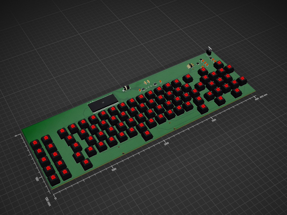
Keyboard is an open-source printed circuit board by jasperhax0r, from the jasperhax0r/CompaqPortableKeyboard repository on GitHub, published under the MIT licence. It is a 2-layer board of 405 × 135 mm with 188 parts on 143 nets, routed with 1,060 tracks and 66 vias.
It is built around the SN74LVC07AD, SN74LVC14AD and PESD5V0S1UL, with the SMAJ15A, SMAJ5.0A and SS14 among its other parts. Its parts include 90 diodes, 83 switches, 7 capacitors, 4 ICs and 2 resistors. It belongs with the keyboards and input boards and the RP2040 boards of this library.
A drop-in replacement keyboard controller for the Compaq Portable (1983),
built around a Raspberry Pi Pico. It reads an 83-key diode matrix and speaks the
machine's native IBM XT (scancode set 1) protocol over the original 2×3
keyboard connector.
The repo also contains a USB-serial / PS-2 test rig used during bring-up, and
— probably the most useful part for other people — a scope-verified writeup of
the Compaq Portable keyboard protocol, which as far as I can tell isn't
documented anywhere else public.
Everything here is hand-solderable through-hole where possible, on purpose. The
only surface-mount parts are the two level-shifter buffers, and even those have a
through-hole alternative described in the build notes.
Why this exists
The original keyboard PCBs are getting old, and the matrix routing on the
factory board is... a journey. This recreates the keyboard's electrical behavior
faithfully enough that the machine POSTs and types exactly as it did in 1983,
while letting you rebuild the board with a $15 iron and a solder sucker.
The first PCB revision is a faithful recreation of the original layout, on
purpose — it's a known-good reference. A rev2 with layout improvements is planned
(see docs/rev2-notes.md).
Repository layout
text
/firmware        Pico firmware (CircuitPython)
  code.py          matrix-scan keyboard firmware (the real thing)
  test-rig/        USB-serial + PS-2 bring-up firmware
/hardware        KiCad project, schematic, PCB, Gerbers
/models          3D-printable STLs (connector keyway + fitment shims)
/tools           protocol decoder + KLE matrix-annotation scripts
  xtframe.py       decode a logic-analyzer CSV into XT scancodes
  kle_annotate.py  annotate a raw KLE layout with matrix coordinates
/docs            protocol writeup, build notes, rev2 log
How it works
The Pico scans a 10×10 diode matrix (83 keys, one diode per key, so full
NKRO) and emits XT scancodes on the keyboard connector.
Power: the Compaq feeds ~12 V down the cable. An onboard 7805 drops that to
5 V for the buffers, and the Pico runs from that 5 V into VSYS through a Schottky.
The board reproduces the original's protection: reverse-polarity Schottky, a
polyfuse, TVS clamps at the connector, and a 5.6 V crowbar across the 5 V rail.
Level shifting: the Pico is 3.3 V and not 5 V tolerant. Outbound
clock/data go through an SN74LVC07A (open-drain, pulled to 5 V). Inbound
reset and clock-sense come back through an SN74LVC14A Schmitt-trigger
cascade — the hysteresis matters, see the protocol notes on line ringing.
Protocol: XT scancode set 1. The keyboard generates the clock; each frame is
one start bit plus 8 data bits, LSB first, with data valid on the falling clock
edge, at roughly 24 kHz. On reset release the keyboard waits ~170 ms then sends
0xAA (self-test passed). Full details and scope captures in
docs/protocol.md.
Building the firmware
The firmware is CircuitPython — no toolchain, no compile step.
Flash CircuitPython to the Pico.
Copy firmware/code.py to the CIRCUITPY drive as code.py.
That's it — it runs on boot.
Bring-up before you install it
code.py has debug switches at the top:
DEBUG = True prints every key make/break to the USB serial console.
RAW_SCAN = True prints the raw (row, col) of every press, ignoring the
keymap — use this to verify your matrix wiring against the board.
XT_CONNECTED = False scans and prints but does not drive the XT lines,
so you can validate the whole matrix over USB with nothing connected to the
Compaq.
Walk every key with RAW_SCAN = True and confirm it matches the board before
trusting the scancode map. When it checks out, set all three back to
DEBUG = False, RAW_SCAN = False, XT_CONNECTED = True.
Note on the matrix map: this board is wired to the original Compaq's
matrix order (a straight sequential fill), not the interleaved mapping a
tool like kbplacer produces from the KLE. If you regenerate the keymap from
the layout file you'll get the wrong table. The map in code.py is the
authoritative one — it was verified key-by-key against the physical board.
Building the board
See docs/build.md for the full walkthrough. The short version:
Populate and verify the regulator section first. Confirm 5.0 V at the rail
and at the buffer VCC pins before any logic sees power.
Power up on a current-limited bench supply (~150 mA limit) for the first
power-on. A wiring fault then shows as the supply hitting its limit at ~0 V,
instead of as a hot regulator and a burn. (Ask me how I know.)
Then the Pico, then the level shifters, then the matrix.
The two SN74LVC0x buffers are TSSOP — the only fine-pitch parts. Drag-solder
with plenty of flux and wick any bridges. If you'd rather stay all-through-hole,
docs/build.md covers a 7407 + CD4050B DIP alternative (you lose the Schmitt
hysteresis on the input side, fine for a short cable).
The 3D-printed parts
/models has the connector keyway (the original connector is mechanically
keyed; the print replicates that so the plug can't seat rotated — important,
since a rotated plug puts 12 V onto a signal line) and fitment shims.
Print in any rigid filament. PETG or ABS if it'll sit near the warm regulator;
PLA is fine otherwise.
Tools
tools/xtframe.py decodes a logic-analyzer CSV (start bit + 8 data LSB-first,
falling-edge sampled) into XT scancodes, with a --deglitch-us option to reject
sub-threshold ringing on a passive tap. It was used to reverse-engineer the
protocol; it's handy for anyone probing an XT-family keyboard.
tools/kle_annotate.py annotates a raw keyboard-layout-editor
JSON with matrix coordinates.
Status
Working. The board POSTs and types on a real Compaq Portable. Known rev1
warts and the planned rev2 fixes are logged in docs/rev2-notes.md
(regulator thermal pad, hand-solder footprints, silkscreen polarity markers,
axial diode on the 5 V rail, and more).
Licenses
This project is open-source hardware. Different parts carry different licenses,
because software, hardware, and documentation are legally distinct:
Part
License
Firmware & tools (/firmware, /tools)
MIT
Hardware & 3D models (/hardware, /models)
CERN-OHL-S v2
Documentation (/docs, this README)
CC-BY-4.0
The firmware is MIT — use it however you like.
The board and STL designs are CERN-OHL-S (strongly reciprocal): if you
make and distribute modified hardware, keep the design files open under the
same terms.
The documentation and protocol writeup are CC-BY-4.0 — reproduce and build
on them, with attribution.
Full texts are in /LICENSES. See CERN-OHL-S §3 for the source-availability
requirement when distributing hardware based on this design.
Acknowledgements
Original Compaq Portable schematic reference: Howard W. Sams & Co.
Computerfacts, 1987 (used for cross-referencing switch designations during
reverse engineering).
Baseboard for remote management of an attached SBC: K64 MCU as USB HID to the target and Ethernet to the workstation, six switched USB-A ports, isolated SPDT relays, level-shifted console, switched target power
It measures 405 × 135 mm and has 2 copper layers, 1.6 mm thick.
What parts does the Keyboard use?
188 parts, built around the SN74LVC07AD, SN74LVC14AD, PESD5V0S1UL and SMAJ15A. The full list of its parts is on this page, with links to each part's symbol and footprint where PCBKit's library has them.
Where can I download the Keyboard KiCad files?
From the jasperhax0r/CompaqPortableKeyboard repository on GitHub, at the commit this page was made from: the board is hardware/Keyboard.kicad_pcb and its schematic hardware/Keyboard.kicad_sch. PCBKit opens the board in the browser, with nothing to install.
Can I use the Keyboard design in my own project?
Its repository publishes it under the MIT licence: you may reuse it on that licence's terms (keep the author's notice, and for a copyleft licence share your changes alike).