2 layers155 × 115 mm
Slider unrouted
positron48/camera-slider
Two stationary stepper motors drive a belt-and-gear mechanism that moves the carriage and rotates the camera platform.
90 parts

 positron48/camera-slider
Two stationary stepper motors drive a belt-and-gear mechanism that moves the carriage and rotates the camera platform.
Slider is an open-source printed circuit board by positron48, from the positron48/camera-slider repository on GitHub. It is a 2-layer board of 155 × 115 mm with 136 parts on 70 nets, routed with 785 tracks and 0 vias.
It is built around the R-78E5.0-1.0, SN74LVC14AD and IRF4905. Its parts include 36 resistors, 23 capacitors, 8 connectors, 5 ICs and 3 transistors. It belongs with the ESP32 and RISC-V boards of this library.


A DIY camera slider with independent linear travel and continuous pan, controlled by an ESP32-C6.
Two stationary stepper motors drive a belt-and-gear mechanism that moves the carriage and rotates the camera platform. Program a move with the rotary encoder, or open Motion Studio in a browser to build keyframe sequences, preview camera motion, and track a fixed point in the scene.
The repository contains the mechanical design, printable parts, KiCad electronics, firmware, and assembly documentation. The current mechanical release is v06, with 10 mm belts and a compact motor bridge.
Mechanical files · Web interface · OLED controls · Electronics · Getting started · Русский обзор
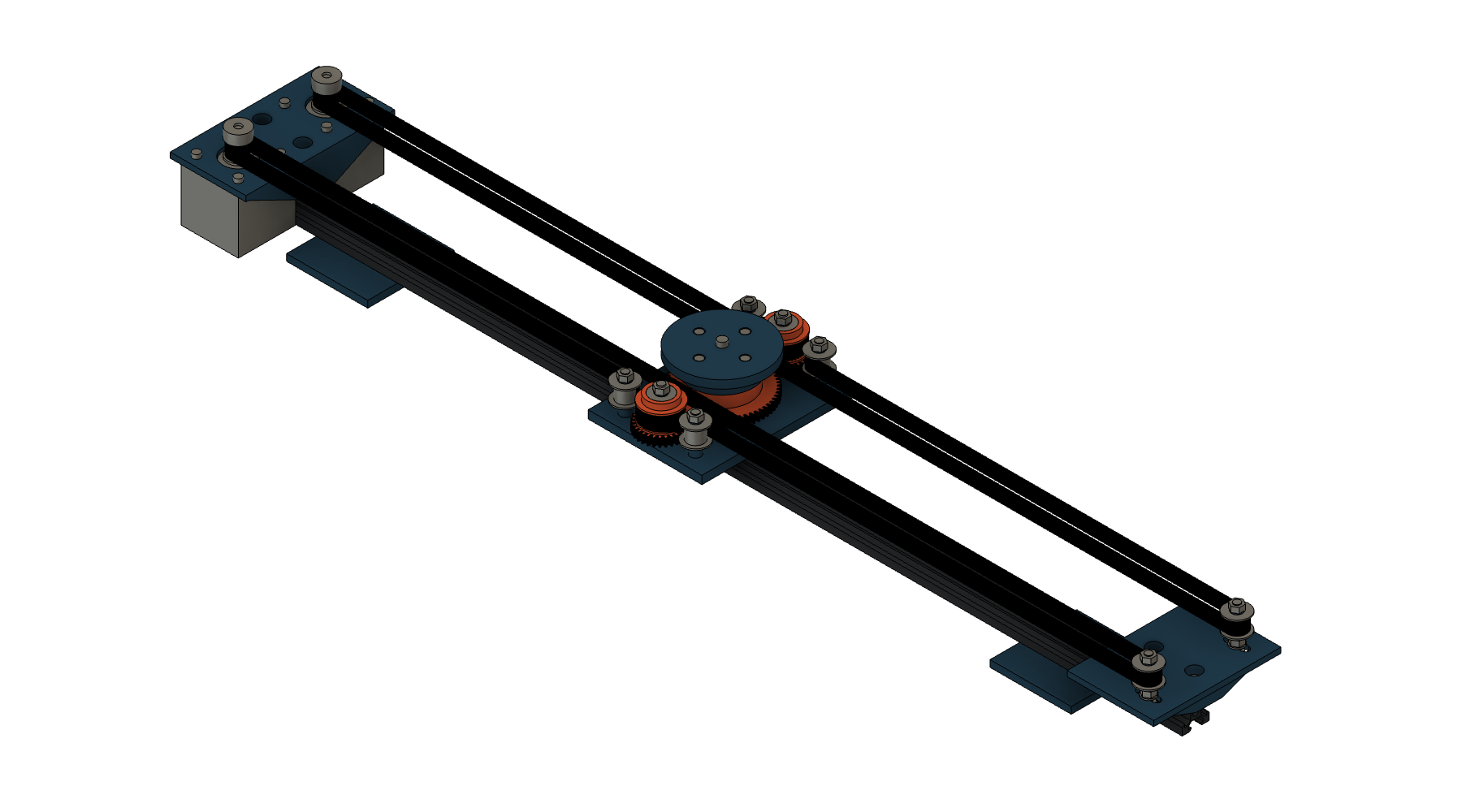
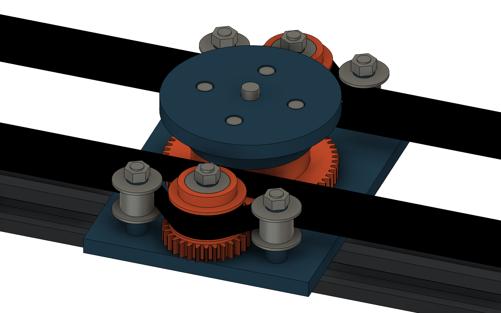
CAD rendering of the v06 assembly. Watch the 37-second demo with English captions · Animation sources
The controller serves its own HTML and JavaScript: no cloud service, account, or internet connection is required. The web interface supports English and Russian. Use the Language / Язык selector in the header; the choice is remembered in this browser. On first visit, Russian browser locales use Russian and other locales use English. OLED menus are in English.
The screenshots below show the actual interface running against a local documentation fixture. Positions, HOME state, SSID, and IP are demonstration data, not a live hardware test.
Choose keyframes on a top-down view of the rail, place target objects, and inspect the camera's orientation before moving anything. The solid camera is the preview; the dashed camera represents the position reported by the controller.
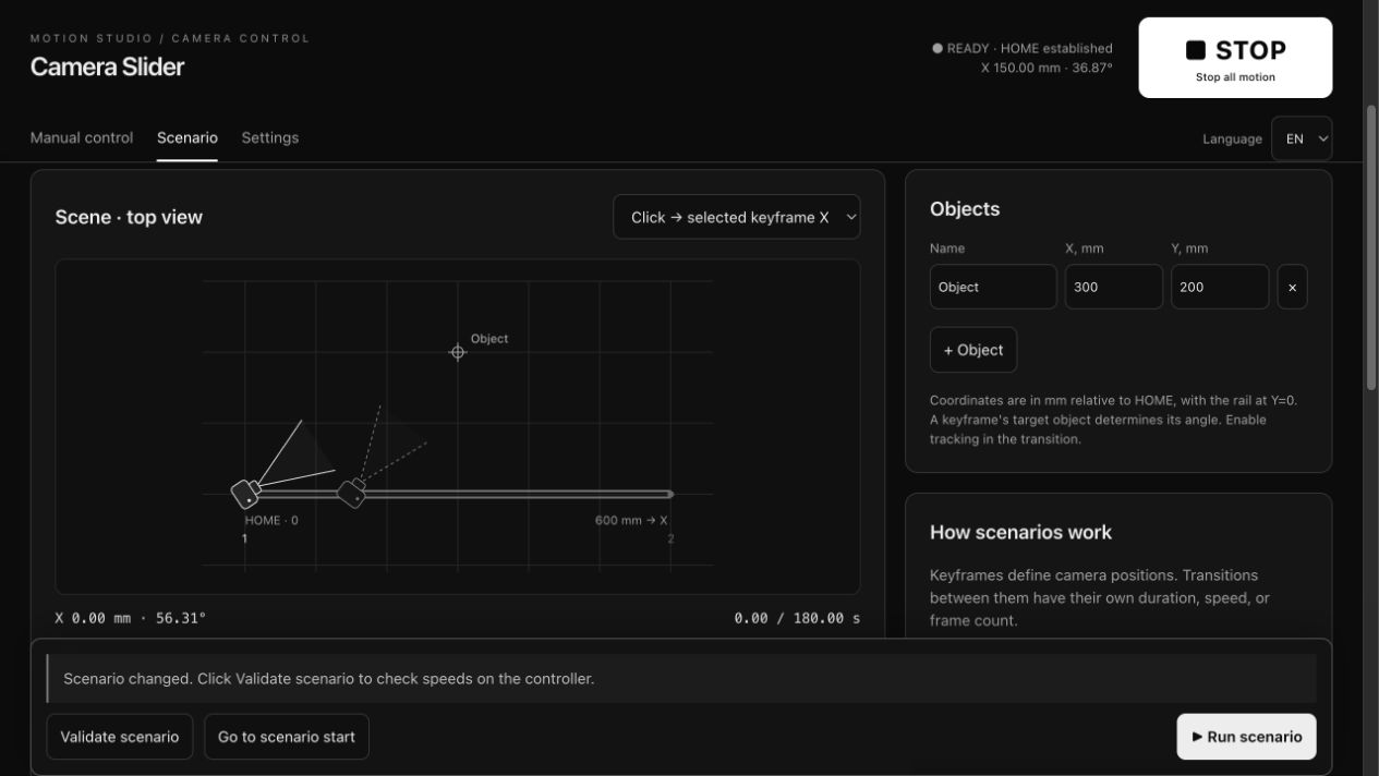
Each transition can use a duration, speed, or frame count. Frame-count timing is calculated as frames / FPS; it does not trigger the camera shutter. Continuous tracking can be enabled separately for each transition.
Try the included object-tracking example: a 600 mm slide around a target at X=300 mm, Y=200 mm over 180 seconds.
Enter an absolute X position and angle, then choose a duration or speed. The interface also provides motor arming, manual HOME, and switch-based homing.
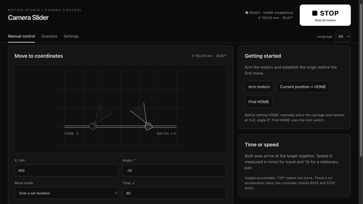
Previewing or editing a scenario does not move the motors. To execute a scenario, establish HOME, validate it, move to its first keyframe, wait for the controller to become ready, and then run it.
Enter your 2.4 GHz Wi-Fi SSID and password under Settings → Connection, then select Save and connect. The credentials are stored on the ESP32 and applied without a reboot. Use Forget network to return to access-point-only operation.
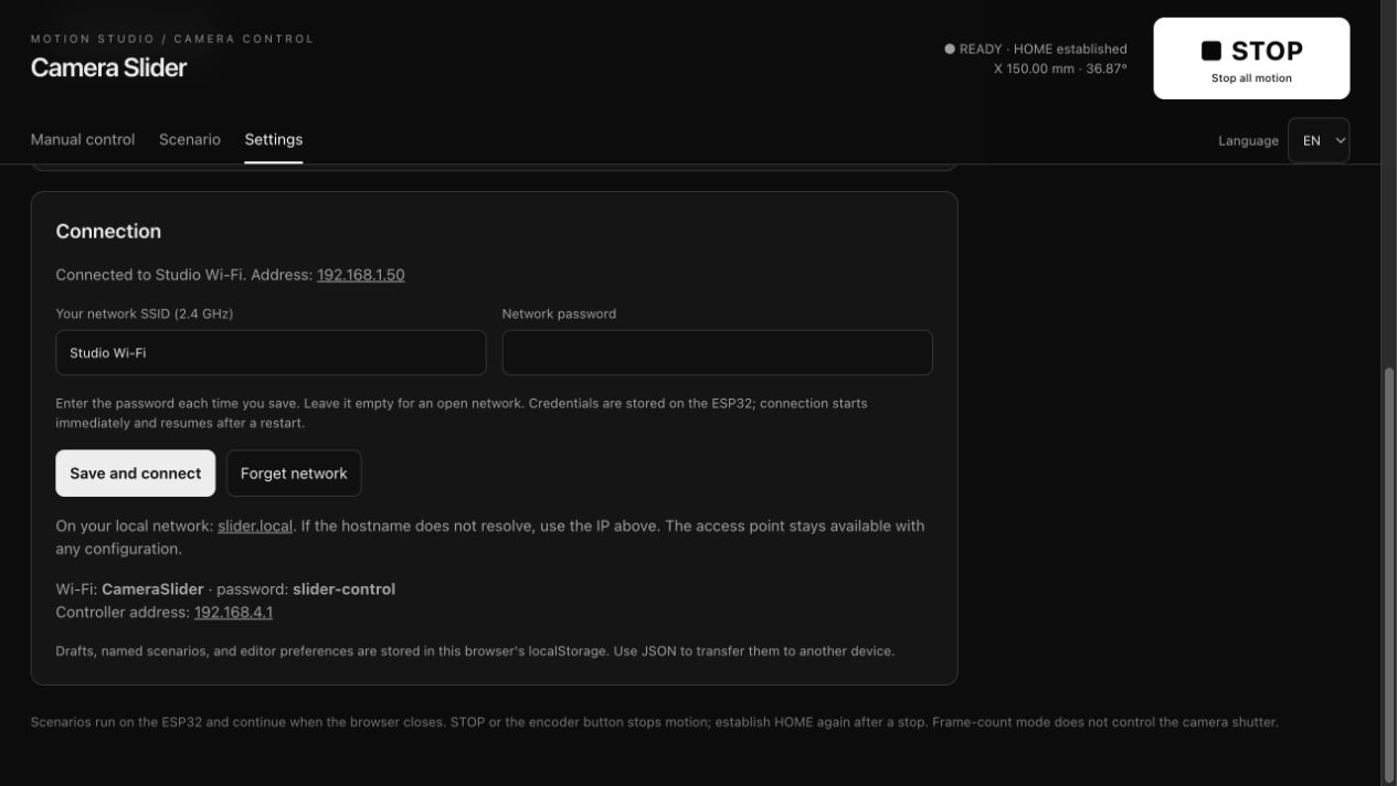
The CameraSlider access point remains enabled even when connected to a router. Failed connections, lost connections, and unfinished DHCP attempts are retried every 30 seconds. A channel change during connection can briefly interrupt an access-point client.
Open http://slider.local from the same local network. If mDNS is blocked or client isolation is enabled, use the IP shown in the connection panel or USB log. The hostname assumes one slider on the network.
| Data | Storage | After a restart |
|---|---|---|
| Encoder scenario: point count, X, angle, transition time | ESP32 NVS | Restored automatically |
| Calibration, travel limit, rates, microsteps, rotation inversion | ESP32 NVS | Restored automatically |
| Wi-Fi SSID and password | ESP32 NVS | Reconnection attempted automatically |
| Web drafts, named scenarios, editor preferences, and interface language | Browser localStorage | Available in the same browser and at the same site address |
| Position, HOME, and execution state | Runtime memory | HOME must be established again; no automatic motion |
The encoder scenario and browser library are separate. Export JSON to transfer browser scenarios between devices or between the AP IP, LAN IP, and slider.local addresses.
Hold the encoder button for about 0.8 seconds to arm the motors. Turn to select an item; click to open it or confirm an edited value. A long press ends editing or returns to the main menu.
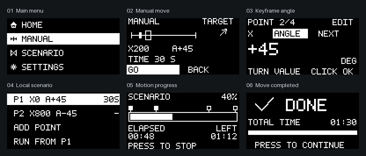
These are pixel-accurate outputs from the firmware's 128×64 display renderer, enlarged 3×. They are not photographs of a physical OLED.
| Menu | Purpose |
|---|---|
HOME | Set the current position to zero without moving, or home against an NC switch |
MANUAL | Set absolute X, accumulated angle, and a move duration |
SCENARIO | Edit 2–8 points, add/delete points, move to a point, or run from point 1 |
SETTINGS | Configure travel, calibration, rates, HOME, per-motor microsteps, and rotation inversion |
POWER OFF | Disable the motor drivers and require arming again |
For local scenarios, NEXT is the time from the selected point to the next one, from 1 to 3600 seconds. Confirm the edited field before switching off power: flash is written on confirmation, not on every encoder detent. A failed write shows SCENARIO SAVE ERROR and can be retried by confirming again.
During motion, the OLED shows progress, passed/upcoming keyframes, elapsed time, and time remaining. A completed move shows DONE. Pressing the encoder during ordinary motion requests a stop; pressing it during automatic homing accepts the current position as HOME.
The v06 design uses a 700 mm V-Slot 2020 rail, a four-wheel carriage, two 17HS4401S NEMA 17 motors, and a 1/4″-20 camera mount. Both motors stay at one end of the rail. The camera platform supports continuous mechanical rotation; the camera and any attached cables must allow it.
| Component | v06 specification |
|---|---|
| Carriage plate | 50 × 50 × 6 mm, four wheels |
| Belts | Two endless 2GT belts, 10 mm wide, nominal 1400 mm pitch length |
| Motor pulleys | Purchased 20T 2GT pulleys, 5 mm bore |
| Carriage transmission | Printed 40T belt pulleys / 30T gears driving a 60T center gear |
| Bearings | Four 625 and two 608 bearings |
| Motor bridge | 110 mm wide; motor shaft spacing 65.3 mm |
| Platform height | 75.7 mm above the table, excluding camera and protruding mounting screw |
| Printed parts | PETG; bearing and belt-profile test coupons included |
The rail length is not the usable travel. Set the firmware travel limit to the actual assembled clearance; the default is 600 mm.
| Resource | Files / documentation |
|---|---|
| Complete mechanical package | v06 release folder and release notes |
| Editable Fusion assembly | camera-slider-v06.f3d |
| Complete STEP assembly | camera-slider-v06.step |
| Individual parts / detail models | STEP parts · STL parts |
| Bill of materials | Parts, quantities, dimensions, and fasteners |
| Assembly instructions | Assembly sequence |
| Print preparation | Print orientation and fit checks |
| Snapmaker U1 project | Prepared plate and slicer settings |
| Transmission | Belt routing and kinematics |
| Design decisions | v06 revision notes |
| CAD source | Python geometry and build scripts |
Detailed mechanical and electronics notes are currently mostly in Russian. Part IDs are consistent across the BOM, STEP/STL files, and CAD generators. Do not mix parts from different revisions.
The Fusion bodies are editable solids. Dimensions are reproduced by the Python generators; Fusion motion joints and a parametric feature timeline are not configured. Older designs remain under cad/ and manufacturing/ for reference.
The controller combines a MuseLab nanoESP32-C6 v1.0, two TMC2209 modules, an SSD1306 I²C OLED, a KY-040 rotary encoder, and one optional normally closed HOME switch.
| Resource | Link |
|---|---|
| KiCad project | slider.kicad_pro |
| Top-level schematic | slider.kicad_sch |
| PCB layout | slider.kicad_pcb |
| Local symbols and footprints | Slider.kicad_sym · Slider.pretty |
| Electronics status and assembly notes | Electronics README |
| Electronics BOM | Component list |
| Module pinout correction | TMC2209 pin mapping notes |
| Firmware wiring reference | Board pin definitions · Detailed wiring guide |
Open the project from the electronics/kicad/ directory so its local libraries resolve. The PCB contains manual layout/routing work. The electronics notes document a driver pinout correction and a required schematic-to-PCB review; archived manufacturing files and old DRC results do not certify the current board. Do not regenerate the PCB over those edits.
| Signal | ESP32-C6 GPIO |
|---|---|
| OLED SDA / SCL | 6 / 7 |
| Motor 1 STEP / DIR / EN | 18 / 19 / 15 |
| Motor 2 STEP / DIR / EN | 20 / 21 / 1 |
| Encoder CLK / DT / button | 10 / 11 / 3 |
| HOME switch | 0 |
The firmware uses STEP/DIR control without TMC2209 UART. Each driver has its own enable signal. The default microstep settings are 1/8 for M1 and 1/32 for M2; set the firmware to match the physical MS1/MS2 straps. Software settings do not change the driver's electrical mode.
Use 12 V for motor power, the board's designated 5 V input or USB for the MCU, and 3.3 V for the OLED and encoder, with a common ground. Check module orientation, coil pairs, VREF/current, and the wiring guide before powering the motors.
SET HOME HERE, or use automatic homing with a correctly wired switch.The firmware uses ESP-IDF 6.0.2, targeting ESP32-C6. From an activated ESP-IDF environment:
cd firmware
idf.py set-target esp32c6
idf.py build
idf.py -p /path/to/serial-port flash monitor
From the repository root, the Makefile provides the equivalent convenience commands:
make build IDF_PATH=/path/to/esp-idf
make upload IDF_PATH=/path/to/esp-idf PORT=/path/to/serial-port
make monitor IDF_PATH=/path/to/esp-idf PORT=/path/to/serial-port
IDF_PATH defaults to ~/esp/esp-idf-v6.0.2. Replace the serial port with your device's port, such as /dev/ttyACM0 or /dev/cu.usbmodemXXXX. Exit the serial monitor with Ctrl+].
| Setting | Default |
|---|---|
| Wi-Fi access point | CameraSlider |
| Access-point password | slider-control |
| Access-point URL | http://192.168.4.1 |
| Local-network URL | http://slider.local or the DHCP IP |
Join CameraSlider and open its URL. You can then configure your own Wi-Fi network in Motion Studio. There is no automatic movement after boot, even when a saved scenario exists.
| Directory | Contents |
|---|---|
| firmware/ | ESP-IDF application, web assets, host tests, and example scenarios |
| cad/v06/ | Geometry, Fusion generation, OpenCascade builds, and validation scripts |
| manufacturing/prototype-v06/ | Released mechanical models, print meshes, BOM, and assembly notes |
| electronics/ | KiCad project, specifications, libraries, and historical reports |
| animation/v06/ | Scene assets, demonstrations, and rendering tools |
| docs/ | README screenshots and reproducible documentation tools |
| references/ | Component photos and dimensional references |
Run the firmware's host checks with a C compiler, Python 3, and Node.js:
python3 firmware/tests/run.py
node firmware/tests/test_web.mjs
The tests cover motion planning, coordinated motor stepping, encoder decoding, HOME and stop behavior, local scenario persistence, Wi-Fi retry/fallback logic with mocked ESP-IDF calls, and display rendering. The web tests cover scenario timing, tracking, JSON migration, and browser storage serialization.
The v06 mechanical package includes reports for solid geometry, belt clearance, gear engagement, motion combinations, and mesh integrity. These checks and host tests do not establish physical payload capacity, missed-step behavior, repeatability, or camera footage quality. The current firmware uses constant-speed motion without acceleration ramps; practical speed and load limits must be established on the assembled mechanism.
For full operating details, see the firmware guide. For screenshot provenance and regeneration, see documentation images. Third-party geometry references are recorded in the v06 source notes.
| Qty | Value | Footprint | References |
|---|---|---|---|
| 12 | 10k | Slider:R_0805_2012Metric | R15, R21, R24, R25, R26, R27, R31, R32, R33, R34, R35, R36 |
| 7 | 100n | Slider:C_0805_2012Metric | C8, C9, C10, C12, C13, C14, C15 |
| 7 | 1k | Slider:R_0805_2012Metric | R20, R41, R42, R43, R44, R45, R46 |
| 6 | 10n | Slider:C_0805_2012Metric | C21, C22, C23, C24, C25, C26 |
| 5 | 100R | Slider:R_0805_2012Metric | R10, R11, R12, R13, R14 |
| 5 | 100k | Slider:R_0805_2012Metric | R1, R16, R17, R18, R19 |
| 5 | 4k7 | Slider:R_0805_2012Metric | R51, R52, R53, R54, R60 |
| 4 | H1, H2, H3, H4 | ||
| 2 | 0R | Slider:R_0805_2012Metric | R22, R23 |
| 2 | 100n 50V | Slider:C_0805_2012Metric | C16, C17 |
| 2 | 220u 35V | Slider:CP_Radial_D8.0mm_P3.50mm | C2, C3 |
| 2 | BSS138 G/S/D | Slider:SOT-23 | Q2, Q3 |
| 2 | MKS TMC2209 V1.0 | Slider:MKS_TMC2209_V1 | U2, U3 |
| 1 | +3V3 | Slider:TESTPOINT | TP3 |
| 1 | +5V | Slider:TESTPOINT | TP2 |
| 1 | 10u | Slider:C_0805_2012Metric | C7 |
| 1 | 10u 16V | Slider:C_0805_2012Metric | C5 |
| 1 | 10u 50V | Slider:C_0805_2012Metric | C4 |
| 1 | 12V INPUT | Slider:POWER_P7.40 | J1 |
| 1 | 12V ZENER K/A | Slider:D_SOD-123 | D2 |
| 1 | 1u | Slider:C_0805_2012Metric | C11 |
| 1 | 470u 35V | Slider:CP_Radial_D10.0mm_P5.00mm | C1 |
| 1 | 47u 16V | Slider:CP_Radial_D6.3mm_P2.50mm | C6 |
| 1 | DISPLAY G V C D | Slider:CONN_4_P2.50 | J7 |
| 1 | DISPLAY VOLTAGE | Slider:HDR_3_P2.54 | JP2 |
| 1 | DRV_EN | Slider:TESTPOINT | TP5 |
| 1 | ENDSTOP1 | Slider:HDR_3_P2.54 | J4 |
| 1 | ENDSTOP2 | Slider:HDR_3_P2.54 | J5 |
| 1 | ENDSTOP3 | Slider:HDR_3_P2.54 | J6 |
| 1 | FUSE HOLDER | Slider:FUSE_WIRES | F1 |
| 1 | GND | Slider:TESTPOINT | TP4 |
| 1 | IRF4905 | Slider:TO-220-3_Vertical | Q1 |
| 1 | KY-040 CABLE | Slider:HDR_5_P2.54 | J8 |
| 1 | MCU POWER | Slider:HDR_2_P2.54 | JP1 |
| 1 | MOTOR1 | Slider:CONN_4_P2.50 | J2 |
| 1 | MOTOR2 | Slider:CONN_4_P2.50 | J3 |
| 1 | MuseLab nanoESP32-C6 v1.0 | Slider:MCU_2x15 | U1 |
| 1 | R-78E5.0-1.0 | Slider:RECOM_SIP3 | U5 |
| 1 | SMBJ15A K/A | Slider:D_SMB | D1 |
| 1 | SN74LVC14AD | Slider:SOIC-14_3.9x8.7mm_P1.27mm | U4 |
| 1 | TMC_UART_BUS | Slider:TESTPOINT | TP6 |
| 1 | VM | Slider:TESTPOINT | TP1 |
| 1 | WIRE +3V3 | Slider:Wire_W37 | W37 |
| 1 | WIRE +3V3 | Slider:Wire_W38 | W38 |
| 1 | WIRE +3V3 | Slider:Wire_W36 | W36 |
| 1 | WIRE +5V | Slider:Wire_W2 | W2 |
| 1 | WIRE DRV_EN | Slider:Wire_W19 | W19 |
| 1 | WIRE ENC_CLK_F | Slider:Wire_W29 | W29 |
| 1 | WIRE ENC_CLK_MCU | Slider:Wire_W20 | W20 |
| 1 | WIRE ENC_CLK_RAW | Slider:Wire_W13 | W13 |
| 1 | WIRE ENC_DT_F | Slider:Wire_W28 | W28 |
| 1 | WIRE ENC_DT_MCU | Slider:Wire_W22 | W22 |
| 1 | WIRE ENC_DT_RAW | Slider:Wire_W30 | W30 |
| 1 | WIRE ENC_SW_F | Slider:Wire_W14 | W14 |
| 1 | WIRE ENC_SW_RAW | Slider:Wire_W11 | W11 |
| 1 | WIRE ES1_F | Slider:Wire_W6 | W6 |
| 1 | WIRE ES1_MCU | Slider:Wire_W5 | W5 |
| 1 | WIRE ES2_F | Slider:Wire_W39 | W39 |
| 1 | WIRE ES2_MCU | Slider:Wire_W33 | W33 |
| 1 | WIRE GND | Slider:Wire_W44 | W44 |
| 1 | WIRE GND | Slider:Wire_W46 | W46 |
| 1 | WIRE GND | Slider:Wire_W43 | W43 |
| 1 | WIRE GND | Slider:Wire_W45 | W45 |
| 1 | WIRE GND | Slider:Wire_W42 | W42 |
| 1 | WIRE GND | Slider:Wire_W41 | W41 |
| 1 | WIRE I2C_SCL_L | Slider:Wire_W15 | W15 |
| 1 | WIRE I2C_SDA_L | Slider:Wire_W27 | W27 |
| 1 | WIRE M1_A1 | Slider:Wire_W24 | W24 |
| 1 | WIRE M1_A2 | Slider:Wire_W31 | W31 |
| 1 | WIRE M1_B1 | Slider:Wire_W40 | W40 |
| 1 | WIRE M1_DIR | Slider:Wire_W17 | W17 |
| 1 | WIRE M1_DIR_MCU | Slider:Wire_W4 | W4 |
| 1 | WIRE M1_STEP | Slider:Wire_W10 | W10 |
| 1 | WIRE M1_STEP_MCU | Slider:Wire_W25 | W25 |
| 1 | WIRE M2_B1 | Slider:Wire_W32 | W32 |
| 1 | WIRE M2_B2 | Slider:Wire_W18 | W18 |
| 1 | WIRE M2_DIR | Slider:Wire_W21 | W21 |
| 1 | WIRE M2_DIR_MCU | Slider:Wire_W3 | W3 |
| 1 | WIRE M2_MS2 | Slider:Wire_W16 | W16 |
| 1 | WIRE M2_STEP | Slider:Wire_W1 | W1 |
The 128 most common of 136 parts.
positron48/camera-slider
Two stationary stepper motors drive a belt-and-gear mechanism that moves the carriage and rotates the camera platform.

positron48/camera-slider
Two stationary stepper motors drive a belt-and-gear mechanism that moves the carriage and rotates the camera platform.

positron48/camera-slider
Two stationary stepper motors drive a belt-and-gear mechanism that moves the carriage and rotates the camera platform.

positron48/camera-slider
Two stationary stepper motors drive a belt-and-gear mechanism that moves the carriage and rotates the camera platform.

positron48/camera-slider
Two stationary stepper motors drive a belt-and-gear mechanism that moves the carriage and rotates the camera platform.

positron48/camera-slider
Two stationary stepper motors drive a belt-and-gear mechanism that moves the carriage and rotates the camera platform.

positron48/camera-slider
Two stationary stepper motors drive a belt-and-gear mechanism that moves the carriage and rotates the camera platform.

positron48/camera-slider
Two stationary stepper motors drive a belt-and-gear mechanism that moves the carriage and rotates the camera platform.

jasperhax0r/CompaqPortableKeyboard
Mechanical Keyboard for the original Compaq Portable XT-Class

SrcnUysl/three-channel-dc-motor-driver-pcb
KiCad-based three-channel DC motor driver and control PCB featuring STM32 interfacing and integrated power management.


owhite/balancing-robot-notes
A control theory and software development repo for a balancing robot.

Sylphiette666/stm32-rfid-smart-bin
STM32F103 and RFID smart mobile bin coursework: assembly guide, mechanical design, wiring, PCB archives and firmware resources

westlicht/performer-hardware
PER|FORMER Eurorack Sequencer - Hardware Design Files


arlyon/rust-matter-led
A Matter-compatible 5-channel RGBCW LED controller built on a custom PCB with an ESP32-C6, written entirely in Rust.
It measures 155 × 115 mm and has 2 copper layers, 1.6 mm thick.
136 parts, built around the R-78E5.0-1.0, SN74LVC14AD and IRF4905. The full list of its parts is on this page, with links to each part's symbol and footprint where PCBKit's library has them.
From the positron48/camera-slider repository on GitHub, at the commit this page was made from: the board is electronics/archive/rev-c-before-simplification-20260914-212133/kicad/slider.kicad_pcb and its schematic electronics/archive/rev-c-before-simplification-20260914-212133/kicad/display.kicad_sch. PCBKit opens the board in the browser, with nothing to install.
Its repository states no licence, so its author keeps all rights: ask positron48 before reusing the design.