2 layers85 × 55 mm
Nixie clock
jason-watkins/nixie-clock
USB-C powered nixie tube clock. Four IN-12B digits, two INS-1 colon lamps, K155ID1 BCD decoder/drivers.
52 partsCC-BY-SA-4.0

 jason-watkins/nixie-clock
USB-C powered nixie tube clock. Four IN-12B digits, two INS-1 colon lamps, K155ID1 BCD decoder/drivers.
Nixie clock is an open-source printed circuit board by jason-watkins, from the jason-watkins/nixie-clock repository on GitHub, published under the CC-BY-SA-4.0 licence. It is a 2-layer board of 70 × 65 mm with 103 parts on 94 nets, routed with 700 tracks and 136 vias.
It is built around the 74LVC1G17Z, ESP32-S3-WROOM-1-N8 and TPS629203DRL, with the TPS63070RNM, TS3USB221ARSE and USBLC6-2SC6 among its other parts. Its parts include 37 resistors, 22 capacitors, 10 diodes, 8 ICs and 8 connectors. It belongs with the lEDs and displays boards and the ESP32 boards of this library.


USB-C powered nixie tube clock. Four IN-12B digits, two INS-1 colon lamps, K155ID1 BCD decoder/drivers.
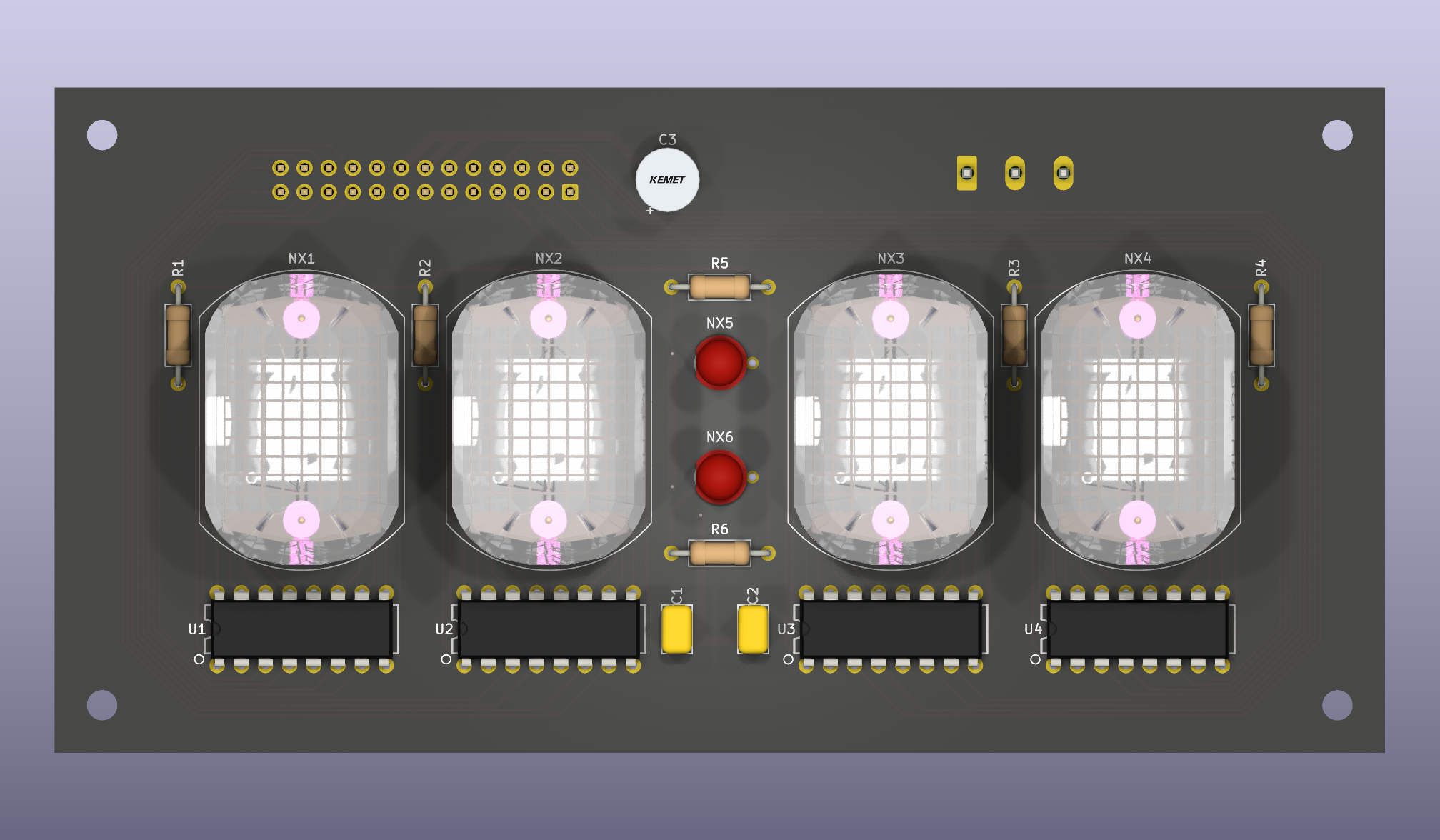
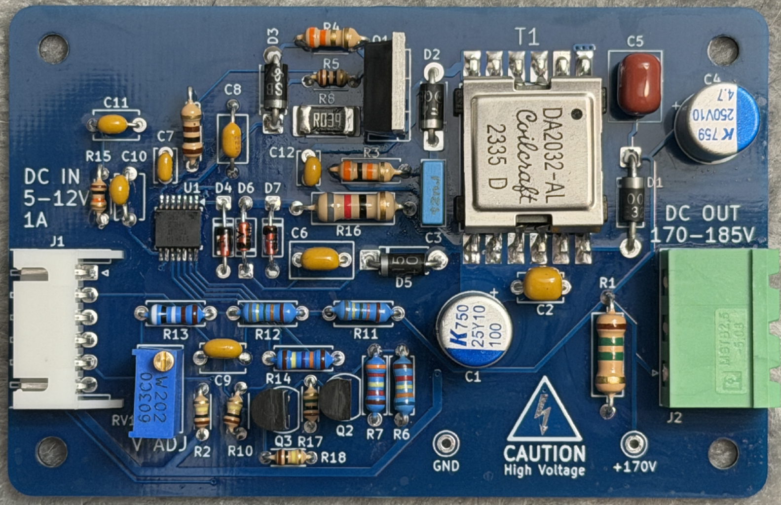
USB-PD negotiates 5-12V supply and feeds it into 3 converters:
Written in Rust, bakes in a list of SSID/password pairs at build time, tries them until one connects, then syncs time from well-known NTP servers and displays US Pacific time in 24 hour format.
Tube cathodes are not wired to the decoder outputs in numerical order. The layout connects each
cathode to whichever decoder output it reaches most directly. The K155ID1's output order around its
package does not match the IN-12B's cathode order around its pin circle, so wiring it that way is
more trouble than it's worth. Firmware maps from BCD number to tube number in nixie::Bcd.
pcb/ KiCad projects. One project each for the clock face, high voltage flyback converter and the
main board with the MCU, USB-PD, 3.3V and 5V converters.pcb/lib/ project libraries; origins and local changes in pcb/lib/README.mdfirmware/ firmware source codedocs/ design doc and vendor datasheetsscripts/ make_release.py, fab exports with enforced revision bookkeepingpython scripts/make_release.py --check
python scripts/make_release.pyWrites gerbers, BOM, and placement files in several formats tailored for
different fab houses under fab/ and tags the commit. The script's docstring
explains the revision rules it enforces.
The K155ID1 symbol and its DIP16 footprint started as imports from judge2005's Eagle-and-KiCAD-Nixie-Libs and were modified here. Full library inventory: pcb/lib/README.md.
AI assistance is used to write and edit documentation, build symbols/footprints, and as a sounding board for design work. All schematic drawing, PCB layout and code is done by hand.
This work is licensed under a Creative Commons Attribution-ShareAlike 4.0 International License.

except for third-party material carrying its own terms:
docs/datasheets/ — manufacturer datasheets and scanned Soviet tube
documentation, redistributed for reference; sources in
docs/tube_notes.md.docs/design_analysis/fonts/ — PT Serif and IBM Plex Mono, under the SIL
Open Font License 1.1.pcb/lib/nixie_clock.3dshapes/; and the section data in
cad/ins1/shoulder_profile.py, sampled from a third-party model. Provenance
in pcb/lib/README.md.| Qty | Value | Footprint | References |
|---|---|---|---|
| 12 | 10k | Resistor_SMD:R_0402_1005Metric | R2, R5, R7, R9, R10, R11, R12, R102, R103, R121, R124, R127 |
| 8 | 100nF | Capacitor_SMD:C_0402_1005Metric | C1, C2, C3, C5, C102, C106, C108, C123 |
| 7 | 100k | Resistor_SMD:R_0402_1005Metric | R6, R104, R112, R113, R122, R123, R129 |
| 4 | 1uF | Capacitor_SMD:C_0402_1005Metric | C103, C104, C105, C107 |
| 4 | 22uF | Capacitor_SMD:C_1206_3216Metric | C4, C125, C132, C133 |
| 4 | MountingHole | MountingHole:MountingHole_3.2mm_M3_ISO7380 | H2, H3, H4, H5 |
| 3 | 2.4k | Resistor_SMD:R_0402_1005Metric | R107, R109, R128 |
| 3 | 680 | Resistor_SMD:R_0402_1005Metric | R3, R4, R8 |
| 3 | GND | TestPoint:TestPoint_Pad_D1.0mm | TP1, TP122, TP132 |
| 2 | 10uF | Capacitor_SMD:C_0805_2012Metric | C121, C131 |
| 2 | 1k | Resistor_SMD:R_0402_1005Metric | R105, R110 |
| 2 | 20k | Resistor_SMD:R_0402_1005Metric | R101, R111 |
| 2 | 5.1k | Resistor_SMD:R_0402_1005Metric | R106, R108 |
| 2 | 74LVC1G17 | Package_TO_SOT_SMD:SOT-23-5 | U1, U2 |
| 1 | +3.3V | LED_SMD:LED_0603_1608Metric | D122 |
| 1 | +3V3 | TestPoint:TestPoint_Pad_D1.0mm | TP121 |
| 1 | +5V | TestPoint:TestPoint_Pad_D1.0mm | TP131 |
| 1 | +5V | LED_SMD:LED_0603_1608Metric | D131 |
| 1 | 1.5uH | 0_nixie_clock:L_Bourns_SRN5040TA | L121 |
| 1 | 10uF | Capacitor_SMD:C_0402_1005Metric | C124 |
| 1 | 10uF | Capacitor_SMD:C_0603_1608Metric | C122 |
| 1 | 120k | Resistor_SMD:R_0402_1005Metric | R125 |
| 1 | 150 | Resistor_SMD:R_0402_1005Metric | R1 |
| 1 | 2.2uH | 0_nixie_clock:L_Bourns_SRN5040TA | L131 |
| 1 | 26 pin IDC | Connector_IDC:IDC-Header_2x13_P2.54mm_Vertical | J4 |
| 1 | 27k | Resistor_SMD:R_0402_1005Metric | R131 |
| 1 | 39k | Resistor_SMD:R_0402_1005Metric | R126 |
| 1 | 4.7uF | Capacitor_SMD:C_0805_2012Metric | C101 |
| 1 | 47uF | Capacitor_SMD:C_1206_3216Metric | C126 |
| 1 | 5.6k | Resistor_SMD:R_0402_1005Metric | R134 |
| 1 | 80.6k | Resistor_SMD:R_0402_1005Metric | R132 |
| 1 | Boot | 0_nixie_clock:SW_Panasonic_EVQ_4.9x4.9mm | SW1 |
| 1 | CYPD3176 | 0_nixie_clock:QFN-24-1EP_4x4mm_P0.5mm_EP2.75x2.75mm_ThermalVias | U103 |
| 1 | Conn_01x06 | Connector_JST:JST_XH_S6B-XH-A_1x06_P2.50mm_Horizontal | J5 |
| 1 | DMP3099L | Package_TO_SOT_SMD:SOT-23-3 | Q122 |
| 1 | ESP32-S3-WROOM-1 | 0_nixie_clock:ESP32-S3-WROOM-1 | U3 |
| 1 | FAULT | LED_SMD:LED_0603_1608Metric | D104 |
| 1 | FDC6312P | Package_TO_SOT_SMD:SOT-23-6 | Q131 |
| 1 | FDS4935A | Package_SO:SOIC-8_3.9x4.9mm_P1.27mm | Q101 |
| 1 | FLASH | Connector_PinHeader_1.27mm:PinHeader_1x02_P1.27mm_Vertical | J7 |
| 1 | I2C | Connector_PinHeader_2.54mm:PinHeader_1x04_P2.54mm_Vertical | J6 |
| 1 | JTAG | 0_nixie_clock:Samtec_FTSH-105-01-L-DV-K_2x05_P1.27mm_Vertical_SMD | J2 |
| 1 | JTAG SRC | Connector_PinHeader_1.27mm:PinHeader_1x02_P1.27mm_Vertical | J3 |
| 1 | MM3Z10VST1G | Diode_SMD:D_SOD-323_HandSoldering | D103 |
| 1 | RX | LED_SMD:LED_0603_1608Metric | D2 |
| 1 | Reset | 0_nixie_clock:SW_Panasonic_EVQ_4.9x4.9mm | SW2 |
| 1 | SD15Q-7 | Diode_SMD:D_SOD-323 | D102 |
| 1 | STATUS | LED_SMD:LED_0603_1608Metric | D3 |
| 1 | TPS629203 | Package_TO_SOT_SMD:SOT-583-8 | U131 |
| 1 | TPS63070 | 0_nixie_clock:VQFN-15_2.5x3mm_TI_RNM0015A | U121 |
| 1 | TS3USB221A | 0_nixie_clock:UQFN-10_1.5x2mm_P0.5mm_TI_RSE0010A | U102 |
| 1 | TX | LED_SMD:LED_0603_1608Metric | D1 |
| 1 | UART | Connector_PinHeader_2.54mm:PinHeader_1x06_P2.54mm_Vertical | J1 |
| 1 | USBLC6-2SC6 | Package_TO_SOT_SMD:SOT-23-6 | U101 |
| 1 | USB_C_Receptacle_USB2.0_16P | 0_nixie_clock:USB_C_Receptacle_JAE_DX07S016JA1R1500 | J101 |
| 1 | VBUS_{C} | TestPoint:TestPoint_Pad_D1.0mm | TP102 |
| 1 | V_{BUSC} | LED_SMD:LED_0603_1608Metric | D101 |
| 1 | V_{BUS} | LED_SMD:LED_0603_1608Metric | D105 |
| 1 | V_{BUS} | TestPoint:TestPoint_Pad_D1.0mm | TP101 |
jason-watkins/nixie-clock
USB-C powered nixie tube clock. Four IN-12B digits, two INS-1 colon lamps, K155ID1 BCD decoder/drivers.

jason-watkins/nixie-clock
USB-C powered nixie tube clock. Four IN-12B digits, two INS-1 colon lamps, K155ID1 BCD decoder/drivers.

takuhoTech/LagopusSystem-2024
Avionics for Human-Powered Aircraft (Japan International Birdman Rally 2024)

lastlxrd/Pogopo
Open-source modular ESP32-S3 handheld console featuring custom hardware, a Sharp Memory LCD, pogopoOS, emulation, motion controls, audio, haptics, and expandable modules.


C-yue28/Flight_Controller
6-layer custom flight controller PCB, incorporating a battery management system (BMS), 6-axis IMU, dedicated BLDC/servo control/power lines, and camera lines. Uses the ESP32-WROOM-1 as the central microcontroller.


planmarks/Skimmer-Detector-PRO
ESP32 Based Wireless Skimmer Detector

sequoia-hope/robot-link
RP2350A + ST60A3H1 60 GHz contactless link dev board (KiCad, generated)
It measures 70 × 65 mm and has 2 copper layers, 1.6 mm thick.
103 parts, built around the 74LVC1G17Z, ESP32-S3-WROOM-1-N8, TPS629203DRL and TPS63070RNM. The full list of its parts is on this page, with links to each part's symbol and footprint where PCBKit's library has them.
From the jason-watkins/nixie-clock repository on GitHub, at the commit this page was made from: the board is pcb/main/main.kicad_pcb and its schematic docs/design_analysis/schematics/3v3.kicad_sch. PCBKit opens the board in the browser, with nothing to install.
Its repository publishes it under the CC-BY-SA-4.0 licence: you may reuse it on that licence's terms (keep the author's notice, and for a copyleft licence share your changes alike).