
4 layers18.1 × 39 mm
Tikk hw
golioth/tikk-hw
sensor/io front panel for low cost keyboard bluetooth breakout
155 parts1CERN-OHL-P-2.0

 Jankyneering/mu-cell22
An open-source SDR base station
Mu cell bb is an open-source printed circuit board by Jankyneering, from the Jankyneering/mu-cell repository on GitHub, published under the CC-BY-SA-4.0 licence. It is a 4-layer board of 65 × 30 mm with 85 parts on 80 nets, routed with 481 tracks and 194 vias.
It is built around the SX1255IWLTRT, 24LC256-E/SN and LDK130M33R, with the CC0402KRX7R7BB104, CC0402KRX7R9BB103 and 0402CS-39NXGRW among its other parts. Its parts include 26 resistors, 25 capacitors, 7 connectors, 4 diodes and 4 inductors. It belongs with the radio and wireless boards of this library.



An open-source SDR base station platform for digital and analog voice modes.
Got a board? Start with the Quick Start Guide.
µCell is a software-defined radio base station/repeater/transceiver that runs on a Raspberry Pi.
The µCell BB board puts an SX1255 transceiver, its RF front-end, and a HAT identification EEPROM on a board that sits on a Pi 3, 4, 5, or Zero 2W. A single command installs the driver, and from there you pick the radio software you want to run.
The board presents itself as a standard SoapySDR device. The project started with TETRA, but DMR, D-Star, YSF, P25, and analog FM run on the same board through MMDVM-IQ, and general-purpose SDR software works with it directly. The goal is to support every voice mode we can reach.
Everything is open. Schematics, PCB layouts, production outputs, 3D printed case designs, drivers, and the EEPROM tooling are all in this repository, under licences that let you build, modify, and sell your own.
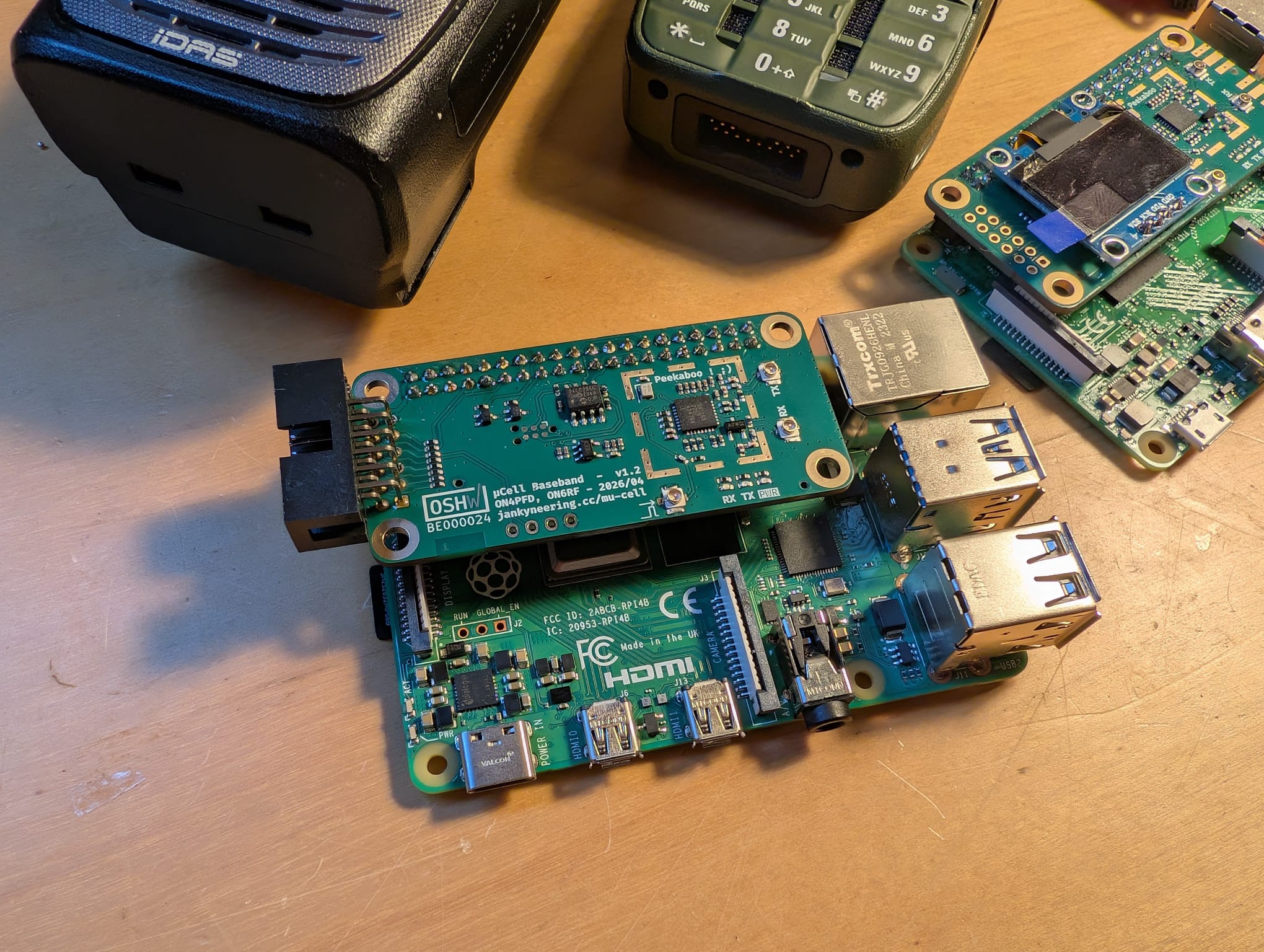
Assembled and tested µCell BB boards are sold by Fred Corp., one half of the Jankyneering team:
Each board sold there is individually measured on an RF test set before shipping, and carries a signed EEPROM so the driver can confirm where it came from. See the FAQ for what signing does and does not mean.
The design is open and the production outputs are in this repository, ready to upload to a PCBA house. Component choice is critical: the RF path depends on inductor Q, capacitor dielectric, and a low drift referenceL. Foregoing proper part selection will affect sensitivity and output power.
See docs/muCellBBManufacture.md for the production package contents, the stackup, the component selection notes, and the EEPROM writing procedure.
The stack has three layers.
mu-cell-bb-drivers contains the device tree overlay that makes the Pi recognise the board, and SoapyMuCell, the hardware driver itself. The install script in this repository builds and installs both.
SoapyMuCell registers with SoapySDR as the device driver=mucell. Any SoapySDR-aware application can open the board without knowing anything about the SX1255. This is the integration point: adding support for new software is usually a matter of pointing it at the right device string.
| Software | Modes | Status |
|---|---|---|
| Flowstation | TETRA, wider feature set, less stable | Supported |
| Tetra-Bluestation | TETRA, stable, fewer features | Supported on the testing branch, landing in main |
| Nexus-BS | TETRA, different development direction than Flowstation | Untested, but claims support |
| MMDVM-IQ | FM, DMR, D-Star, YSF, P25, POCSAG | Supported |
Each of these is its own project with its own installation instructions.
General-purpose SDR software reaches the board the same way, through the driver=mucell device string:
| Software | Status |
|---|---|
| GQRX | Supported |
| CubicSDR | Supported |
| GNU Radio | Should work through the Soapy blocks, more testing needed |
| SDR++ | Needs a dedicated source module, not yet written |
The quick start guide covers how to point each one at the board.
| Document | Covers |
|---|---|
| Quick Start Guide | Flash a Pi, install the driver, set up your radio software, get on air |
| Building the Drivers | The driver and overlay built by hand, step by step, no scripts |
| Hardware | Board specifications, connectors, measured performance, cases, roadmap |
| Manufacturing | Production outputs, component selection, EEPROM writing and signing |
| FAQ | Common questions, support routes, the "not genuine" warning |
Contributions are welcome. For small fixes or documentation updates, feel free to open a pull request directly. For larger changes, open an issue first so the approach can be discussed. Keep pull requests focused and include a clear description of what changed and why.
Hardware contributions follow the same route. If you are proposing a layout or component change, include the reasoning and, where relevant, the measurements that back it up.
Support for a new mode or a new piece of SDR software is always of interest. If you get something working against driver=mucell, a short section for the quick start guide is a welcome contribution on its own.
µCell builds on the work of several open-source projects:
We also acknowledge the broader SDR and SoapySDR communities whose work enables hardware experimentation with modern radio systems.
Certified open source hardware by OSHWA under registration BE000024

Hardware and documentation published under CreativeCommons BY-SA 4.0
 Creative Commons Attribution-ShareAlike 4.0 International License
Software published under GNU GPLv3
| Qty | Value | Footprint | References |
|---|---|---|---|
| 15 | 100R | Resistor_SMD:R_0402_1005Metric_Pad0.72x0.64mm_HandSolder | R1, R2, R3, R4, R5, R6, R7, R19, R20, R21, R22, R23, R24, R25, R26 |
| 9 | 100n | Capacitor_SMD:C_0402_1005Metric_Pad0.74x0.62mm_HandSolder | C7, C9, C10, C11, C12, C14, C16, C21, C24 |
| 6 | 10n | Capacitor_SMD:C_0402_1005Metric_Pad0.74x0.62mm_HandSolder | C13, C15, C17, C18, C19, C22 |
| 5 | 1K | Resistor_SMD:R_0402_1005Metric_Pad0.72x0.64mm_HandSolder | R14, R15, R16, R17, R18 |
| 4 | 100p | Capacitor_SMD:C_0402_1005Metric_Pad0.74x0.62mm_HandSolder | C1, C2, C6, C8 |
| 4 | MountingHole_M3_3.2mm_Pad | PCM_SL_Mechanical:MountingHole_3.2mm_Pad | H1, H2, H3, H4 |
| 3 | 1M | Resistor_SMD:R_0402_1005Metric_Pad0.72x0.64mm_HandSolder | R8, R9, R10 |
| 3 | 39n | Inductor_SMD:L_0402_1005Metric_Pad0.77x0.64mm_HandSolder | L1, L3, L4 |
| 3 | 3K9 | Resistor_SMD:R_0402_1005Metric_Pad0.72x0.64mm_HandSolder | R11, R12, R13 |
| 2 | clipboard:e7774905-3e1b-474f-b2b7-99bac235eba3 | , | |
| 2 | 1u | Capacitor_SMD:C_0402_1005Metric_Pad0.74x0.62mm_HandSolder | C20, C23 |
| 2 | BC817-40W | Package_TO_SOT_SMD:SOT-323_SC-70 | Q1, Q2 |
| 2 | TC2030 | Connector:Tag-Connect_TC2030-IDC-NL_2x03_P1.27mm_Vertical | J6, J7 |
| 2 | ~ | OSHW:OSHW-Certification-Mark-Stacked_8x7mm_SilkMask | BE000024, BE000024 |
| 1 | 22n | Inductor_SMD:L_0402_1005Metric_Pad0.77x0.64mm_HandSolder | L2 |
| 1 | 24LC256 | Package_SO:SOIC-8_3.9x4.9mm_P1.27mm | U1 |
| 1 | 3.3p | Capacitor_SMD:C_0402_1005Metric_Pad0.74x0.62mm_HandSolder | C3 |
| 1 | 38.4MHz | Crystal:Crystal_SMD_2016-4Pin_2.0x1.6mm | Y1 |
| 1 | 4.7u | Capacitor_SMD:C_0402_1005Metric_Pad0.74x0.62mm_HandSolder | C25 |
| 1 | 6.8p | Capacitor_SMD:C_0402_1005Metric_Pad0.74x0.62mm_HandSolder | C5 |
| 1 | 8.2p | Capacitor_SMD:C_0402_1005Metric_Pad0.74x0.62mm_HandSolder | C4 |
| 1 | Amber | PCM_LED_SMD_AKL:LED_0402_1005Metric_Pad0.77x0.64mm | LED2 |
| 1 | BAV99,215 | Package_TO_SOT_SMD:SOT-23-3 | D1 |
| 1 | CLK_SEL | Jumper:SolderJumper-3_P1.3mm_Bridged12_RoundedPad1.0x1.5mm_NumberLabels | JP1 |
| 1 | EXT_CLK | parts:U.FL_Vertical_GND | J3 |
| 1 | GND | parts:2118707-4 CAN | RFCAN1 |
| 1 | Green | PCM_LED_SMD_AKL:LED_0402_1005Metric_Pad0.77x0.64mm | LED3 |
| 1 | IO | Connector_IDC:IDC-Header_2x06_P2.54mm_Horizontal | J5 |
| 1 | LDK130M33R | parts:SOT23-5L_1P75X3P05X0P95_STM | U2 |
| 1 | RPi GPIO | Connector_PinSocket_2.54mm:PinSocket_2x20_P2.54mm_Vertical | J4 |
| 1 | RX | parts:U.FL_Vertical_Passthrough | J2 |
| 1 | Red | PCM_LED_SMD_AKL:LED_0402_1005Metric_Pad0.77x0.64mm | LED1 |
| 1 | SSD1306 | parts:OLED_128x64_I2C | OLED1 |
| 1 | SX1255IWLTRT | parts:QFN50P500X500X80-33N-D | IC1 |
| 1 | TX | parts:U.FL_Vertical_Passthrough | J1 |
| 1 | WP | Jumper:SolderJumper-2_P1.3mm_Open_RoundedPad1.0x1.5mm | JP2 |
The 84 most common of 85 parts.
golioth/tikk-hw
sensor/io front panel for low cost keyboard bluetooth breakout


Seeed-Studio/OSHW-reCamera-Series
reCamera is a series of open-source AI cameras.

embeddedos-org/eCAD-Hardware-Products
Hardware designs + EE docs + Board datasheets of Multiple products

Natchpai/LQRx-InterleavedBuck
Digitally Controlled 2-phase Interleaved Buck Converter


It measures 65 × 30 mm and has 4 copper layers, 1.61 mm thick.
85 parts, built around the SX1255IWLTRT, 24LC256-E/SN, LDK130M33R and CC0402KRX7R7BB104. The full list of its parts is on this page, with links to each part's symbol and footprint where PCBKit's library has them.
From the Jankyneering/mu-cell repository on GitHub, at the commit this page was made from: the board is hardware/mu-cell-bb/mu-cell-bb.kicad_pcb and its schematic hardware/mu-cell-bb/mu-cell-bb.kicad_sch. PCBKit opens the board in the browser, with nothing to install.
Its repository publishes it under the CC-BY-SA-4.0 licence: you may reuse it on that licence's terms (keep the author's notice, and for a copyleft licence share your changes alike).