

4 layers91 × 30 mm
Methanesense
fredriknk/msense
Open Source hardware kicad source files for a NRF9160 based methane sensor utilizing MOX sensor.
145 partsMIT

 Natchpai/LQRx-InterleavedBuck3
Digitally Controlled 2-phase Interleaved Buck Converter
2Phase SynchBuck is an open-source printed circuit board by Natchpai, from the Natchpai/LQRx-InterleavedBuck repository on GitHub, published under the CERN-OHL-S-2.0 licence. It is a 4-layer board of 100 × 67 mm with 306 parts on 176 nets, routed with 1,599 tracks and 797 vias.
It is built around the ACS37030LLZATR-040B3, UCC27282DRCT and SPX3819M5-L-3-3/TR, with the GRM31CR71H475KA12, RC0603JR-070RL and GRM21BZ7YA475KE15 among its other parts. Its parts include 103 capacitors, 86 resistors, 16 diodes, 10 ICs and 8 transistors. It belongs with the power boards and the STM32 boards of this library.


A two-phase interleaved synchronous buck converter controlled by an STM32G474RET6 using state-space Linear Quadratic Regulator (LQR) feedback.
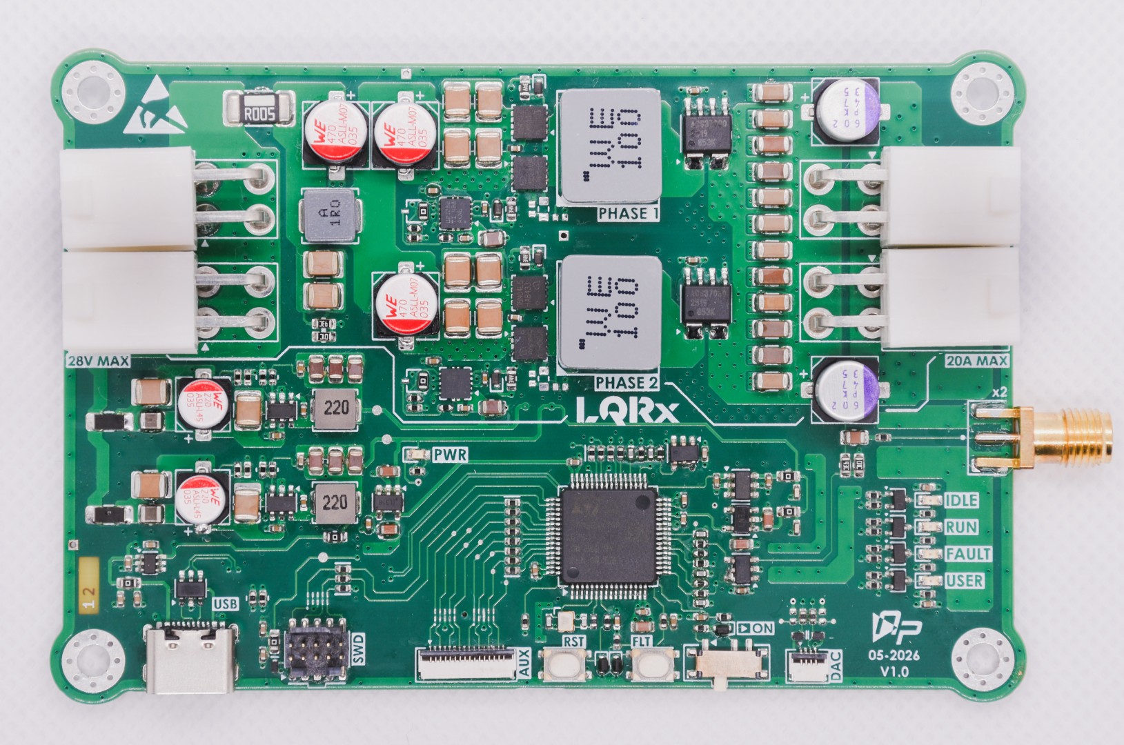
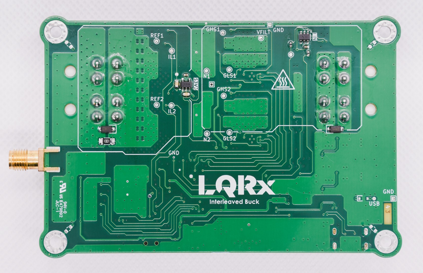
| Parameter | Specification |
|---|---|
| Input voltage | 24 VDC nominal, 28 V maximum |
| Output voltage | 12 VDC nominal; the reference voltage can be changed |
| Maximum load current | 20 A total, 10 A per phase |
| Output power | 200 W+ continuous rating |
| Switching frequency | 200 kHz per phase |
| Equivalent ripple frequency | 400 kHz with 180° interleaving |
| Controller | STM32G474RET6, state feedback |
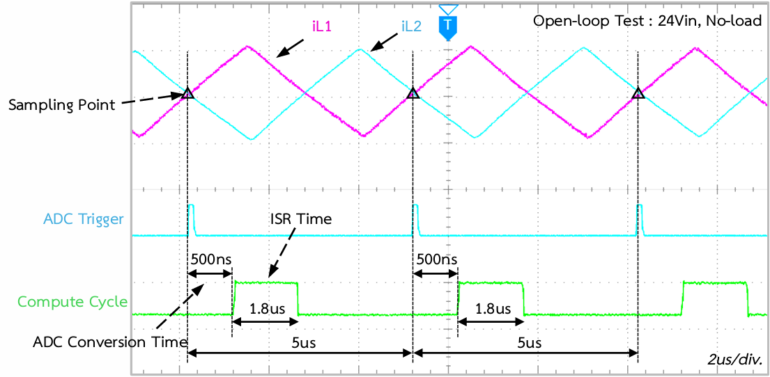
| Firmware execution time | Approximately 1.8µs per cycle at a 5 µs sampling period, measured on v1.0 |
Specifications describe design targets unless explicitly identified as measured or verified results.
Current Phase: RELEASE
| Phase | Description |
|---|---|
| DRAFT | Schematic design in progress |
| PRELIMINARY | Schematic nearly complete; PCB design started |
| CHECK | Design mostly finalized; human-led verification |
| RELEASE | Human-approved design baseline released |
The project owner declares the current phase. It does not independently establish design correctness or approval.
flowchart LR
    A["DRAFT<br/>Schematic Design"]
    B["PRELIMINARY<br/>Schematic Finalization<br/>PCB Design"]
    C["CHECK<br/>Design Docs<br/>ERC / DRC<br/>Human Review"]
    D["RELEASE<br/>Approved Design<br/>Baseline Publication"]

    A --> B
    B --> C
    C --> D

    classDef inactive fill:#334155,color:#ffffff,stroke:#64748b
    classDef review fill:#b45309,color:#ffffff,stroke:#92400e
    classDef done fill:#15803d,color:#ffffff,stroke:#166534

    class A done
    class B done
    class C done
    class D done
Slate: not started, Amber: current phase, Green: completed
The design uses two interleaved synchronous buck power phases and an STM32G474RET6 controller. The controller uses state-space LQR feedback with integral action and delay compensation.
2Phase_SynchBuck/
├── README.md
├── LICENSE
├── 2Phase_SynchBuck.kicad_pro
├── 2Phase_SynchBuck.kicad_sch
├── 2Phase_SynchBuck.kicad_pcb
├── Block_diagram.kicad_sch
├── Interface_interconnects.kicad_sch
├── MCU_IOs.kicad_sch
├── MCU_power.kicad_sch
├── RevHistory.kicad_sch
├── Top_hierarchical.kicad_sch
├── analog_frontEnd.kicad_sch
├── powerSupplies.kicad_sch
├── power_connectors.kicad_sch
├── power_state.kicad_sch
├── pwr_sequencing.kicad_sch
├── user_LED.kicad_sch
├── user_interface.kicad_sch
├── Library/
├── Templates/
└── documents/
    ├── Images/
    ├── Manufacturing/
    ├── Schematics/
└── Simulation/| Resource | Description |
|---|---|
| Board top view | PCB render |
| Board bottom view | PCB render |
| Assembly drawing | Assembly output |
| Bill of materials | BOM for revision 1.1 |
| Fabrication documents | Fabrication drawing |
| Gerber files | Fabrication output |
| Schematic PDF | Schematic output |
| Buck simulation | Simulation file |
| LC filter simulation | Simulation file |
| LC filter supply simulation | Simulation file |
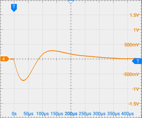
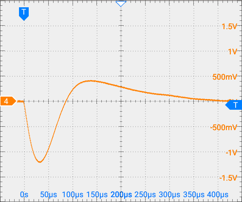
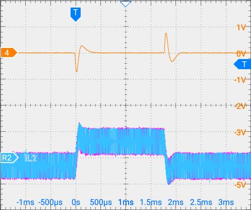
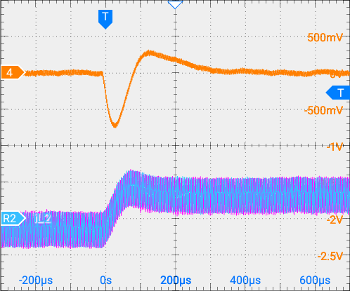
Measurements below were taken on the v1.0 physical board.
| Result | Measurement conditions | Value |
|---|---|---|
| Load regulation | 24 V input, 0–10 A load | 0.124% |
| Line regulation | 16–28 V input, 10 A fixed load | 0.033% |
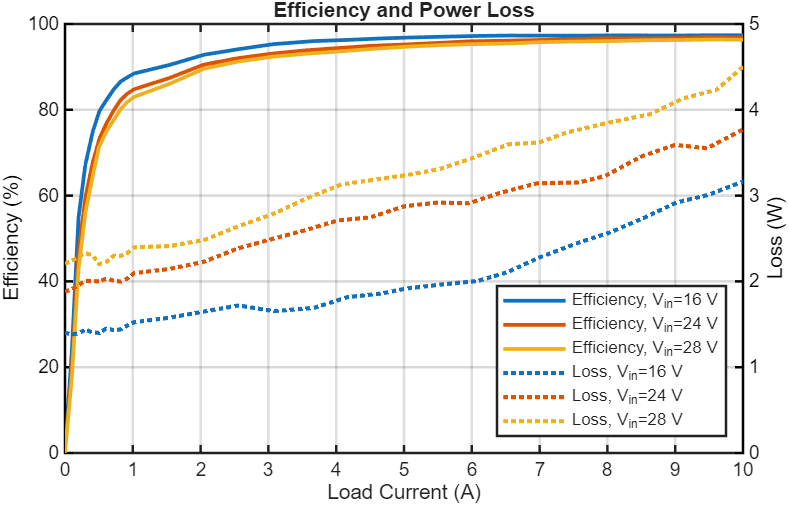
| Maximum efficiency | 16, 24, and 28 V input; 0–10 A load. Peak at 16 V input, 12 V output, and 8 A output load | 97.4% |
| Firmware execution time | 5 µs sampling period | Approximately 1.8µs per cycle |
Measurement captures:
| Efficiency sweep |
|---|
 |
| 6 A load response | 12 A load response |
|---|---|
 |  |
| 6 A load & Current Balancing | Zoomed |
|---|---|
 |  |
| Open-loop compute-time test |
|---|
 |
Copyright (c) 2026 Natchpai.
The hardware design files are licensed under CERN-OHL-S-2.0.
The complete licence text is available in:
CERN Open Hardware Licence Version 2 - Strongly Reciprocal
| Qty | Value | Footprint | References |
|---|---|---|---|
| 43 | 100n | 0_C_SMD:C_0402_nomDensity | C107, C108, C109, C114, C117, C119, C120, C121, C126, C129, C145, C304, C305, C306, C313, C314 +27 |
| 20 | 22R | 0_R_SMD:R_0402_nomDensity | R102, R103, R501, R503, R504, R505, R506, R705, R706, R707, R708, R709, R710, R711, R712, R713 +4 |
| 14 | 4u7 | 0_C_SMD:C_1210_nomDensity | C101, C102, C110, C111, C112, C113, C122, C123, C124, C125, C301, C303, C310, C312 |
| 12 | 4u7 | 0_C_SMD:C_1206_nomDesity | C130, C131, C132, C133, C134, C135, C137, C138, C139, C140, C141, C142 |
| 9 | 0R | 0_R_SMD:R_0603_nomDensity | R311, R313, R401, R701, R704, R718, R719, R720, R721 |
| 8 | 100R | 0_R_SMD:R_0402_nomDensity | R105, R111, R604, R805, R806, R807, R808, R902 |
| 8 | 4u7 | 0_C_SMD:C_0805_nomDensity | C106, C118, C307, C308, C309, C316, C317, C318 |
| 7 | 2u2 | 0_C_SMD:C_0603_nomDensity | C319, C321, C322, C324, C326, C327, C401 |
| 7 | 49R9 | 0_R_SMD:R_0402_nomDensity | R202, R507, R508, R601, R602, R603, R605 |
| 6 | 100k | 0_R_SMD:R_0402_nomDensity | R106, R112, R809, R810, R811, R812 |
| 6 | 21k5 | 0_R_SMD:R_0402_nomDensity | R104, R110, R304, R306, R308, R310 |
| 5 | 1k | 0_R_SMD:R_0402_nomDensity | R502, R802, R803, R903, R905 |
| 5 | 1n | 0_C_SMD:C_0402_nomDensity | C601, C602, C603, C604, C605 |
| 4 | 04A2 | 0_Conn:Molex_Mini-Fit_Jr_5569-04A2_2x02_P4.20mm_Horizontal | CN201, CN202, CN203, CN204 |
| 4 | 2R21 | 0_R_SMD:R_0603_nomDensity | R107, R108, R113, R114 |
| 4 | BAT54XV2T5G | 0_SOD:D_SOD-523 | D101, D102, D103, D104 |
| 4 | GS2N7002KW | 0_SOT:SOT-323_SC-70 | Q801, Q802, Q803, Q804 |
| 4 | MountingHole_Pad | 0_miscellaneous:MountingHole_3.2mm_M3_Pad_Via | H701, H702, H703, H704 |
| 3 | 47u | 0_C_SMD:CP_Elec_6.3x5.5_WCAP-ASLI | C103, C104, C105 |
| 3 | 5k11 | 0_R_SMD:R_0402_nomDensity | R312, R702, R703 |
| 3 | EN | 0_net_tie:NetTie-2_SMD_Pad0.15mm | NT303, NT304, NT305 |
| 3 | ESD5Z3V3 | 0_SOD:D_SOD-523 | D901, D902, D903 |
| 3 | GND | 0_testpoints:TestPoint_THTPad_1.0x1.0mm_Drill0.5mm | TP113, TP114, TP307 |
| 3 | PUSB3FR4Z | 0_SOT:SOT1176-2-_1x2.5mm_P0.5mm | D702, D703, D704 |
| 3 | SP3031-01ETG | 0_SOD:D_SOD-882 | D701, D705, D706 |
| 2 | 100p | 0_C_SMD:C_0402_nomDensity | C116, C128 |
| 2 | 10k | 0_R_SMD:R_0603_nomDensity | R117, R119 |
| 2 | 10k | 0_R_SMD:R_0402_nomDensity | R901, R904 |
| 2 | 10u | 0_inductor:744393665100 | L102, L103 |
| 2 | 20m | 0_R_SMD:R_PA1206_R004-R020_YAGEO | R301, R302 |
| 2 | 22u | 0_inductor:AMDLA4020S | L302, L304 |
| 2 | 22u | 0_C_SMD:CP_Elec_5x5.5_WCAP-ASLI | C302, C311 |
| 2 | 2u2 | 0_inductor:L_0806_BDCD00201610 | L301, L303 |
| 2 | 47u | 0_C_SMD:CP_Elec_6.3x6_OS-CON-SVPK | C136, C143 |
| 2 | 499 | 0_R_SMD:R_0402_nomDensity | R801, R804 |
| 2 | 6p8 | 0_C_SMD:C_0402_nomDensity | C501, C502 |
| 2 | 90k9 | 0_R_SMD:R_0603_nomDensity | R116, R118 |
| 2 | ACS37030LLZATR-040B3 | 0_ACS3703X:ACS37030LLZA | U102, U104 |
| 2 | BSZ018N04LS6 | 0_infineon_MOSFET:PG-TSDSON-8-26 | Q101, Q103 |
| 2 | Green | 0_LED:LED_0603_1608Metric | LD301, LD802 |
| 2 | IQE013N04LM6 | 0_infineon_MOSFET:PG-TSON-8-4 | Q102, Q104 |
| 2 | LMR54410DBVR | 0_SOT:SOT-23-6 | U301, U302 |
| 2 | N/A | 0_C_SMD:C_0402_nomDensity | C115, C127 |
| 2 | N/A | 0_R_SMD:R_0603_nomDensity | R109, R115 |
| 2 | Orange | 0_LED:LED_0603_1608Metric | LD801, LD804 |
| 2 | SMF4L28A | 0_SOD:D_SOD-123FL | D201, D202 |
| 2 | SPX3819M5-L-3-3/TR | 0_SOT:SOT-23-5 | U303, U304 |
| 2 | SW_Tactile_PTS815SJM250 | 0_switch:SW_Tactile_PTS815SJM250 | B901, B902 |
| 2 | TLV9061SIDBVR | 0_SOT:SOT-23-5 | U601, U602 |
| 2 | UCC27282DRC | 0_gateDrivers:10-VSON(3x3)-DRC | U101, U103 |
| 2 | sw node | 0_net_tie:NetTie-2_SMD_Pad0.2mm | NT103, NT104 |
| 1 | +3V3 | 0_testpoints:TestPoint_NoSlik_D1.0mm_Top | TP304 |
| 1 | +5V | 0_testpoints:TestPoint_NoSlik_D1.0mm_Top | TP302 |
| 1 | +9V | 0_testpoints:TestPoint_NoSlik_D1.0mm_Top | TP301 |
| 1 | +A3V3 | 0_testpoints:TestPoint_NoSlik_D1.0mm_Bottom | TP305 |
| 1 | +S3V3 | 0_testpoints:TestPoint_NoSlik_D1.0mm_Bottom | TP306 |
| 1 | +USB | 0_testpoints:TestPoint_NoSlik_D1.0mm_Bottom | TP303 |
| 1 | 110k | 0_R_SMD:R_0402_nomDensity | R307 |
| 1 | 118k | 0_R_SMD:R_0402_nomDensity | R309 |
| 1 | 162k | 0_R_SMD:R_0402_nomDensity | R303 |
| 1 | 1k | 0_R_SMD:R_1206_YEGEO | R201 |
| 1 | 1u | 0_C_SMD:C_0805_nomDensity | C201 |
| 1 | 1u | 0_inductor:AMPLH5030S | L101 |
| 1 | 221k | 0_R_SMD:R_0402_nomDensity | R305 |
| 1 | 5m | 0_R_SMD:R_PA2512_R005-R006_YAGEO | R101 |
| 1 | ABM11W-24MHz-8 | 0_crystal:ABM11W_2.0x1.6mm | X501 |
| 1 | Analog VIN | 0_testpoints:TestPoint_NoSlik_D0.5mm_Bottom | TP602 |
| 1 | Analog Vout | 0_testpoints:TestPoint_NoSlik_D0.5mm_Top | TP601 |
| 1 | BAT60JFILM | 0_SOD:D_SOD-323 | D301 |
| 1 | Conn_JTAG_STDC10 | 0_Conn:BD_2x05_P1.27mm_Vertical_SMD | CN702 |
| 1 | DAC1 | 0_testpoints:TestPoint_NoSlik_D0.5mm_Top | TP709 |
| 1 | DAC2 | 0_testpoints:TestPoint_NoSlik_D0.5mm_Top | TP710 |
| 1 | FFC2B28-04-G | 0_Conn_FFC:GCT_FFC2B28-04_P0.5_FFC-4 | CN704 |
| 1 | FFC2B28-16-G | 0_Conn_FFC:GCT_FFC2B28-16_P0.5_FFC-16 | CN703 |
| 1 | GND | 0_testpoints:TestPoint_NoSlik_D0.5mm_Top | TP603 |
| 1 | GND | 0_testpoints:TestPoint_NoSlik_D0.5mm_Bottom | TP604 |
| 1 | Gate HS 1 | 0_testpoints:TestPoint_Pad_D1.0mm_Bottom | TP101 |
| 1 | Gate HS 2 | 0_testpoints:TestPoint_Pad_D1.0mm_Bottom | TP103 |
| 1 | Gate LS 1 | 0_testpoints:TestPoint_Pad_D1.0mm_Bottom | TP102 |
| 1 | Gate LS 2 | 0_testpoints:TestPoint_Pad_D1.0mm_Bottom | TP104 |
The 272 most common of 306 parts.
fredriknk/msense
Open Source hardware kicad source files for a NRF9160 based methane sensor utilizing MOX sensor.

fredriknk/ssense-lte
This is the kicad template i use for my projects. The latest addition is a buildoutputs.py automating picture generation, 3d models and sch/prints, Gerbers ETC! Pretty sweet!


andreapiccini/spaghettilab-community
SpaghettiLab is an open modular hardware and software ecosystem for rapid prototyping, embedded systems development, and product innovation.
It measures 100 × 67 mm and has 4 copper layers, 1.58 mm thick.
306 parts, built around the ACS37030LLZATR-040B3, UCC27282DRCT, SPX3819M5-L-3-3/TR and GRM31CR71H475KA12. The full list of its parts is on this page, with links to each part's symbol and footprint where PCBKit's library has them.
From the Natchpai/LQRx-InterleavedBuck repository on GitHub, at the commit this page was made from: the board is 2Phase_SynchBuck.kicad_pcb and its schematic 2Phase_SynchBuck.kicad_sch. PCBKit opens the board in the browser, with nothing to install.
Its repository publishes it under the CERN-OHL-S-2.0 licence: you may reuse it on that licence's terms (keep the author's notice, and for a copyleft licence share your changes alike).