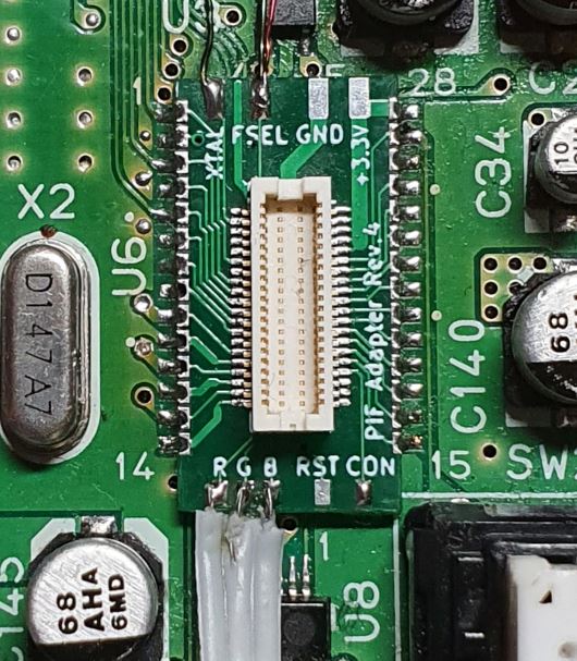
2 layers12 × 12 mm

 jago85/UltraPIF_Hardware79
N64 PIF Replacement Hardware (KiCad)
Pif fpga is an open-source printed circuit board by jago85, from the jago85/UltraPIF_Hardware repository on GitHub, published under the GPL-3.0 licence. It is a 2-layer board of 35 × 41 mm with 61 parts on 67 nets, routed with 1,043 tracks and 169 vias.
It is built around the STM32F070CBT6, W25Q128JVPIQ and 74LVC1G14Z, with the SI5351A-B-GT among its other parts. Its parts include 27 capacitors, 10 resistors, 5 ICs, 4 connectors and 1 inductor. It belongs with the fPGA and programmable logic boards and the STM32 and FPGA and CPLD boards of this library.


The UltraPIF is a replacement for the N64 PIF-NUS chip.
The PIF-NUS chip responsible for region lockout and copy protection. But it also has essential features like game controller access, cartridge EEPROM access and it includes the MIPS CPU boot rom.
The UltraPIF can replace all functions of the original PIF, but ignores the CIC and thus enables a region-free N64. In addition the UltraPIF comes with an integrated clock generator to compensate the differences of the video clocks for NTSC and PAL consoles. The UltraPIF includes an SPI NOR FLASH used to store the N64 software images. At the moment the FLASH is 16 MiB in size and 99% empty, so there could be features like backup and restore of savegame data or even direct emulation of SI (serial interface) hardware (ControllerPak, cart EEPROM, RTC). An RGB LED replaces the original N64 power LED and is used to show if the N64 is running in NTSC or PAL mode. The color is user programmable.
The project consists of custom PCBs, an FPGA design, an MCU firmware and a bunch of software for the N64 itself.
In this repository you find the KiCad hardware files.
You can find hints for assembly and installation in the wiki.



| Qty | Value | Footprint | References |
|---|---|---|---|
| 14 | 100n | Capacitor_SMD:C_0603_1608Metric | C4, C6, C7, C8, C9, C10, C11, C12, C13, C14, C15, C16, C17, C22 |
| 6 | 100n | Capacitor_SMD:C_0402_1005Metric | C20, C23, C24, C25, C26, C27 |
| 6 | 10k | Resistor_SMD:R_0603_1608Metric | R1, R2, R15, R16, R17, R18 |
| 5 | Jumper_NO_Small | Jumper:SolderJumper-2_P1.3mm_Open_RoundedPad1.0x1.5mm | JP1, JP2, JP3, JP4, JP5 |
| 3 | 4u7 | Capacitor_SMD:C_0603_1608Metric | C5, C18, C19 |
| 3 | LED_Small | LED_SMD:LED_0603_1608Metric | LD1, LD2, LD3 |
| 3 | TEST_1P | pif_fpga:TP_0.8mm | TP1, TP2, TP3 |
| 2 | 1u | Capacitor_SMD:C_0603_1608Metric | C2, C21 |
| 2 | 220 | Resistor_SMD:R_0603_1608Metric | R5, R10 |
| 2 | 330 | Resistor_SMD:R_0603_1608Metric | R13, R14 |
| 2 | TestPoint | pif_fpga:TP_0.8mm | TP4, TP5 |
| 1 | 10n | Capacitor_SMD:C_0603_1608Metric | C3 |
| 1 | 10u | Capacitor_SMD:C_0805_2012Metric | C1 |
| 1 | 25 MHz | Crystal:Crystal_SMD_3225-4Pin_3.2x2.5mm | Y1 |
| 1 | 74LVC1G14 | Package_TO_SOT_SMD:SOT-353_SC-70-5 | U5 |
| 1 | CONN_01X05 | pif_fpga:PinHeader_1x05_P2.54mm_NoSolder | P4 |
| 1 | CONN_01X06 | pif_fpga:PinHeader_1x06_P2.54mm_NoSolder | P3 |
| 1 | CONN_01X18 | pif_fpga:Molex_BackFlip_18x0.5mm | P2 |
| 1 | CONN_02X20 | pif_fpga:Hirose_DF12A-40DS-0.5V_2x20_P0.50mm_Vertical | P1 |
| 1 | Ferrite | Inductor_SMD:L_0603_1608Metric | L1 |
| 1 | LCMXO2-2000HC | Package_QFP:TQFP-100_14x14mm_P0.5mm | U2 |
| 1 | STM32F070CBT6 | Package_QFP:LQFP-48_7x7mm_P0.5mm | U3 |
| 1 | Si5351A | Package_SO:MSOP-10_3x3mm_P0.5mm | U1 |
| 1 | W25Q128JVPIQ | Package_DFN_QFN:DFN-8-1EP_6x5mm_P1.27mm_EP2x2mm | U4 |


richardklingler/usbthermocouple
This is my first ever published project on Github, so most probably not error free (o;

dgrubb/Jaguar-USB-tap
Schematics, PCBs and firmware for an Atari Jaguar controller to USB adapter, based on an STM32F07 ARM uC.


apfaudio/sandflat
Lower-cost DSP experimentation host for the SoldierCrab ECP5 SoM

RadioThermal/RadioThermal_Soldering_OSHW
Open Source Hardware 470KHz Induction Soldering Iron


It measures 35 × 41 mm and has 2 copper layers, 1.6 mm thick.
61 parts, built around the STM32F070CBT6, W25Q128JVPIQ, 74LVC1G14Z and SI5351A-B-GT. The full list of its parts is on this page, with links to each part's symbol and footprint where PCBKit's library has them.
From the jago85/UltraPIF_Hardware repository on GitHub, at the commit this page was made from: the board is pif_fpga/pif_fpga.kicad_pcb. PCBKit opens the board in the browser, with nothing to install.
Its repository publishes it under the GPL-3.0 licence: you may reuse it on that licence's terms (keep the author's notice, and for a copyleft licence share your changes alike).