
2 layers35 × 41 mm

 dgrubb/Jaguar-USB-tap8
Schematics, PCBs and firmware for an Atari Jaguar controller to USB adapter, based on an STM32F07 ARM uC.
Jaguar USB tap is an open-source printed circuit board by dgrubb, from the dgrubb/Jaguar-USB-tap repository on GitHub, published under the GPL-3.0 licence. It is a 2-layer board of 70 × 45 mm with 24 parts on 47 nets, routed with 349 tracks and 16 vias.
It is built around the STM32F070CBT6. Its parts include 9 capacitors, 5 connectors, 3 resistors, 2 ICs and 2 diodes. It belongs with the retro computing and games boards and the STM32 boards of this library.

The controller for the Atari Jaguar game console is a strange beast and doesn't map well to modern controllers (in large part due to the numeric keypad). This makes emulating games on a PC with off-the-shelf controllers, which usually mimic PlayStation or XBox layouts, somewhat cumbersome. One possible solution is to create a device which can convert the Jaguar controller's pinout and signals to a USB HID device.
The hardware was developed using the open-source schematic and PCB design tool KiCad. It sports an STM32F070 ARM Cortex M0 micro-controller which handles input from the Jaguar gamepad and generate appropriate USB HID signalling.
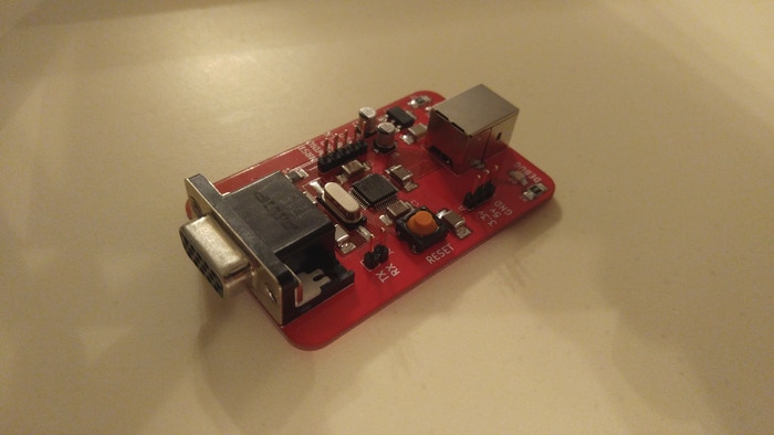
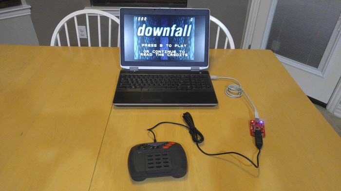
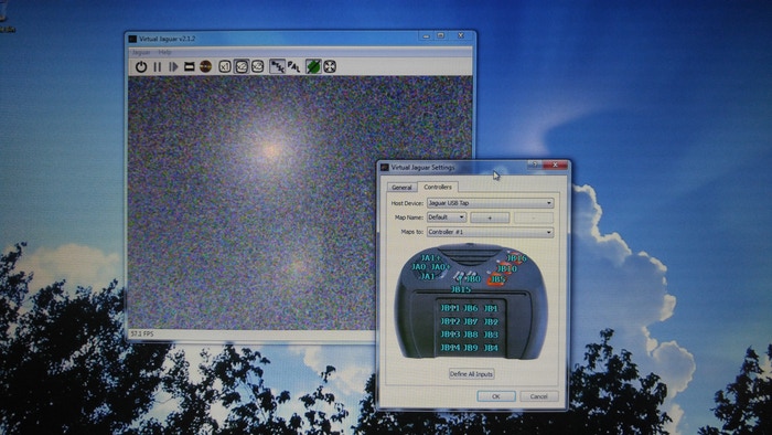
Even though the design uses entirely surface-mount (SMD) components, with the exception of connectors, I selected components with relatively large footprints such as 1812 for non-polarised capacitors. Larger components resulted in the PCB being bigger than it needs to be, but I feel this to be an acceptable trade-off to ensure that the design is accessible as they require less skill to solder and can also be identified and handled more easily by those with poorer eyesight.
At the heart of the board is an STM32F070 microcontroller. This part contains an ARM processor core, a USB peripheral and a small handful of GPIO pins making it highly suited as an embedded processor in USB human-interface devices (HID). While the part is a good technical fit for the project there are also accessibility reasons for using an STM32 uC. Chiefly, firmware can be developed using entirely open-source tools, such as gcc, on the user’s platform of choice (Linux, Mac OS or, I suppose, even Windows).
I've tested on:
In all cases the default USB HID driver on each system is suitable for use with the Jaguar USB Tap and enumerates correctly without additional drivers.
Requires an ARM toolchain:
On Debian/Ubuntu:
$ sudo apt-get install gcc-arm-none-eabi gdb-arm-none-eabi openocdTo build the application:
$ makeTo delete compiled objects and binaries:
$ make cleanTo flash the STM32F0 over STLink:
$ make uploadTo run the debugger, start an OpenOCD session with the target:
$ make debugand then, in another terminal window:
$ make run_gdb| Qty | Value | Footprint | References |
|---|---|---|---|
| 5 | 0.1uF | Capacitors_SMD:C_1812_HandSoldering | C2, C3, C4, C6, C12 |
| 2 | 10uF | Capacitors_SMD:CP_Elec_4x5.8 | C8, C11 |
| 2 | 20pF | Capacitors_SMD:C_1812_HandSoldering | C1, C5 |
| 2 | 650 | Resistors_SMD:R_1210_HandSoldering | R1, R2 |
| 2 | LED | LEDs:LED_1206 | D1, D2 |
| 1 | 10K | Resistors_SMD:R_1210_HandSoldering | R3 |
| 1 | 8MHz | Crystals:Crystal_SMD_HC49-SD_HandSoldering | Y1 |
| 1 | CONN_01X02 | Pin_Headers:Pin_Header_Straight_1x02_Pitch2.54mm | J4 |
| 1 | CONN_01X03 | Pin_Headers:Pin_Header_Straight_1x03_Pitch2.54mm | J1 |
| 1 | CONN_01X05 | Pin_Headers:Pin_Header_Straight_1x05_Pitch2.54mm | J7 |
| 1 | DB15_FEMALE_HighDensity | DB15-SPC15430:conn_SPC15430 | J6 |
| 1 | LOGO | Symbols:OSHW-Logo_19x20mm_SilkScreen | G*** |
| 1 | NCP1117ST33T3G | TO_SOT_Packages_SMD:SOT-223 | U1 |
| 1 | STM32F070CBT6 | Housings_QFP:LQFP-48_7x7mm_Pitch0.5mm | U2 |
| 1 | SW_DPST_x2 | Buttons_Switches_THT:SW_PUSH_6mm | SW1 |
| 1 | USB_B | Connectors:USB_B | J5 |

richardklingler/usbthermocouple
This is my first ever published project on Github, so most probably not error free (o;


dotnet/iot
This repo includes .NET Core implementations for various IoT boards, chips, displays and PCBs.

pascallanger/DIY-Multiprotocol-TX-Module
Multiprotocol TX Module (or MULTI-Module) is a 2.4GHz transmitter module which controls many different receivers and models.


rusefi/rusefi
rusefi - GPL internal combustion engine control unit

DraftShift/StealthChanger
Tool changing system for Vorons and other front mount printer motion systems, not just stealthburner.
It measures 70 × 45 mm and has 2 copper layers, 1.6 mm thick.
24 parts, built around the STM32F070CBT6. The full list of its parts is on this page, with links to each part's symbol and footprint where PCBKit's library has them.
From the dgrubb/Jaguar-USB-tap repository on GitHub, at the commit this page was made from: the board is Hardware/Jaguar-USB-tap.kicad_pcb. PCBKit opens the board in the browser, with nothing to install.
Its repository publishes it under the GPL-3.0 licence: you may reuse it on that licence's terms (keep the author's notice, and for a copyleft licence share your changes alike).