2 layers70 × 110 mm

 jadenrhee/JRWatch2
Low-power BLE wearable: nRF52840 module + nPM1300 PMIC + BMI270 IMU + Sharp MIP display. 36 mm 4-layer board, ~15 µA projected sleep current, Zephyr firmware.
JRWatch is an open-source printed circuit board by jadenrhee, from the jadenrhee/JRWatch repository on GitHub. It is a 4-layer board of 36 × 36 mm with 47 parts on 43 nets, routed with 542 tracks and 182 vias.
It is built around the MDBT50Q-1MV2, BMI270 and USBLC6-2SC6, with the NPM1300-QEAA-R7, ESD9B3.3S and ESD9B5.0S among its other parts. Its parts include 23 capacitors, 8 resistors, 4 ICs, 4 connectors and 2 diodes. It belongs with the radio and wireless and lEDs and displays boards and the nRF52 and nRF5x boards of this library.


A smartwatch designed from scratch, board included. 36 mm across and 4 layers, with an nRF52840 for Bluetooth, an nPM1300 handling charging and the power rails, a BMI270 for motion, and a Sharp memory-in-pixel LCD that holds a static image on about 12 µW. Firmware runs on Zephyr.
Most of the design work went into idle current, meaning what it draws while sitting on a wrist doing nothing.
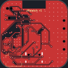
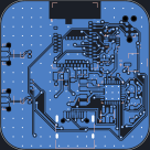
Front copper on the left, back on the right. 36 x 36 mm, 4 layers.
| Sleep current | ~15 µA, or ~26 µA while advertising over Bluetooth (1.5 s interval, not connected) |
| Battery life | ~4 months connected to a phone all day, ~8 months mostly idle, on a 150 mAh cell |
| Firmware | Zephyr v4.1.0, 232 KiB flash / 40 KiB RAM |
These are calculated from datasheet typicals, not measured on hardware. The full itemization is in the verification report. Part choices are in the design rationale.
flowchart LR
  USB["USB-C"]
  BAT["LiPo 150 mAh<br/>+ 10k NTC"]
  PMIC["nPM1300<br/>charger, 2 bucks,<br/>2 load switches"]
  MCU["nRF52840<br/>MDBT50Q-1MV2"]
  DISP["Sharp LS013B7DH03<br/>128 x 128 MIP"]
  IMU["Bosch BMI270"]

  USB -->|VBUS| PMIC
  BAT -->|VBAT| PMIC
  PMIC -->|3V0 always-on| MCU
  PMIC -->|VDD_DISP via LSW1| DISP
  PMIC -->|VDD_IMU via LSW2| IMU

  MCU -.->|I2C 0x6b| PMIC
  MCU -.->|SPI2| DISP
  MCU -.->|SPI1| IMU
Solid lines are power, dashed are data. The display and IMU sit behind
load switches inside the PMIC. In armed sleep they draw about 4 µA and
6 µA. Ship mode disconnects the battery entirely and the whole watch
drops to 370 nA, low enough that cell self-discharge dominates. Full net
list is in hardware/skidl/jrwatch.py.
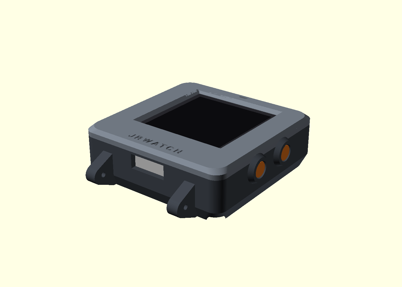
Not yet fabricated. A review before ordering turned up a problem with the display connector, and both halves of it trace to one cause. The panel's ribbon exits the center and has to fold 180 degrees back underneath. That fold leaves roughly a 9 mm window where the connector can sit, and mine was outside it. The fold also inverts the contact face, which reverses the pin order, and I had the pins running straight through.
The pin order is corrected in the schematic. Repositioning the connector is a layout change and hasn't landed yet, so ordering is blocked. Written up as D-025 in the decision log.
An out-of-tree Zephyr board port with devicetree, Kconfig, and board files. Three power modes cover active, armed sleep, and off. The display redraws only when its content changes, and the IMU wakes the SoC on motion. BLE reports battery level and step count (protocol).
| Qty | Value | Footprint | References |
|---|---|---|---|
| 9 | 100nF | C_0402_1005Metric | C4, C11, C13, C14, C15, C18, C19, C21, C23 |
| 6 | 10uF | C_0603_1608Metric | C1, C2, C5, C7, C8, C12 |
| 5 | 1uF | C_0402_1005Metric | C6, C9, C10, C20, C22 |
| 2 | 100R | R_0402_1005Metric | R7, R8 |
| 2 | 100k | R_0402_1005Metric | R5, R6 |
| 2 | 12pF | C_0402_1005Metric | C16, C17 |
| 2 | 2.2uH | L_Murata_DFE201612E_2016 | L1, L2 |
| 2 | 4.7k | R_0402_1005Metric | R3, R4 |
| 1 | 10k NTC | R_0402_1005Metric | RT1 |
| 1 | 150k | R_0402_1005Metric | R2 |
| 1 | 2.2uF | C_0603_1608Metric | C3 |
| 1 | 32.768kHz | Crystal_SMD_3215-2Pin_3.2x1.5mm | Y1 |
| 1 | 47k | R_0402_1005Metric | R1 |
| 1 | BMI270 | Bosch_LGA-14_3x2.5mm_P0.5mm | U3 |
| 1 | ESD9B3.3 | D_SOD-923 | D2 |
| 1 | ESD9B5.0 | D_SOD-923 | D1 |
| 1 | FH12A-10S-0.5SH | Hirose_FH12-10S-0.5SH_1x10-1MP_P0.50mm_Horizontal | J2 |
| 1 | MDBT50Q-1MV2 | Raytac_MDBT50Q | U1 |
| 1 | PWR/SHIP | SW_Push_1P1T-MP_NO_Horizontal_Alps_SKRTLAE010 | SW1 |
| 1 | SM02B-SRSS-TB | JST_SH_SM02B-SRSS-TB_1x02-1MP_P1.00mm_Horizontal | J3 |
| 1 | TC2030-IDC-NL | Tag-Connect_TC2030-IDC-NL_2x03_P1.27mm_Vertical | J4 |
| 1 | TYPE-C-31-M-12 | USB_C_Receptacle_HRO_TYPE-C-31-M-12 | J1 |
| 1 | USBLC6-2SC6 | SOT-23-6 | U4 |
| 1 | USER | SW_Push_1P1T-MP_NO_Horizontal_Alps_SKRTLAE010 | SW2 |
| 1 | nPM1300-QEAA-R7 | VQFN-32-1EP_5x5mm_P0.5mm_EP3.5x3.5mm_ThermalVias | U2 |


JanClyde05/Road-Accident-Monitoring-System
This directory contains the planning, specification, and initial KiCad project for RAMS Wearable PCB Revision C. Do not fabricate from this directory yet -- manual schematic wiring and DRC verification are still needed.

mburger89/SMK_Keyboard_DevKit
59-key hot-swap mechanical keyboard PCB carrier for a socketed ESP32-C6-DevKitC-1 dev board — KiCad project generated/routed by Python scripts

uguryildirim24/elicio
Unfinished ear-muscle EMG earpiece research with KiCad board designs, parametric shell CAD, firmware, synthetic transport fixtures and an audited gesture-to-action gate.

fcoury/knuckles
An open-source, wireless column-staggered ergonomic keyboard.

claudiofin/smartbag
Tagless smart insert for a handbag: recognises its contents with an IR camera, 60 GHz radar and a 96-taxel FSR floor. PCB, CAD, renders and films all generated by script (KiCad -> CadQuery -> Blender).

jacksterb1234/Smart_Watch
A fully custom smartwatch designed from the ground up, featuring a purpose-built PCB, BLE connectivity, and a 3D-printed case. Designed for complete control over hardware and software integration.
It measures 36 × 36 mm and has 4 copper layers, 0.8 mm thick.
47 parts, built around the MDBT50Q-1MV2, BMI270, USBLC6-2SC6 and NPM1300-QEAA-R7. The full list of its parts is on this page, with links to each part's symbol and footprint where PCBKit's library has them.
From the jadenrhee/JRWatch repository on GitHub, at the commit this page was made from: the board is hardware/jrwatch.kicad_pcb. PCBKit opens the board in the browser, with nothing to install.
Its repository states no licence, so its author keeps all rights: ask jadenrhee before reusing the design.