2 layers97.6 × 67.3 mm

 jadenrhee/wigglecam-controller
RP2040 co-processor board for a 4-lens wigglegram camera: constant-current flash, controls, battery telemetry, Pi 5 I2C interface. 4-layer, DRC-clean, fab-ready.
Wigglecam is an open-source printed circuit board by jadenrhee, from the jadenrhee/wigglecam-controller repository on GitHub. It is a 4-layer board of 76 × 50 mm with 105 parts on 67 nets, routed with 929 tracks and 188 vias.
It is built around the RP2040, INA219AID and LM358, with the W25Q128JVSIQ, AP2112K-3.3 and USBLC6-2SC6 among its other parts. Its parts include 35 capacitors, 35 resistors, 8 connectors, 6 ICs and 6 diodes. It belongs with the RP2040 boards of this library.


The RP2040 board that handles timing-critical and analog work for a 4-lens camera. The Raspberry Pi runs capture and image processing, but Linux is not a real-time OS and the Pi can't drive the flash directly.
This board runs the LED flash at constant current, with the limits set in the circuit rather than only in firmware. It also debounces the shutter, decodes the EC11 encoder, and monitors battery voltage and current through an INA219. On a trigger it pulses the Pi the instant the LEDs reach full current.
The Pi drives it over I2C at 0x17, and the capture pulse returns on its own GPIO line. The 2x6 header maps 1:1 onto Pi 5 GPIO pins 1 to 12.
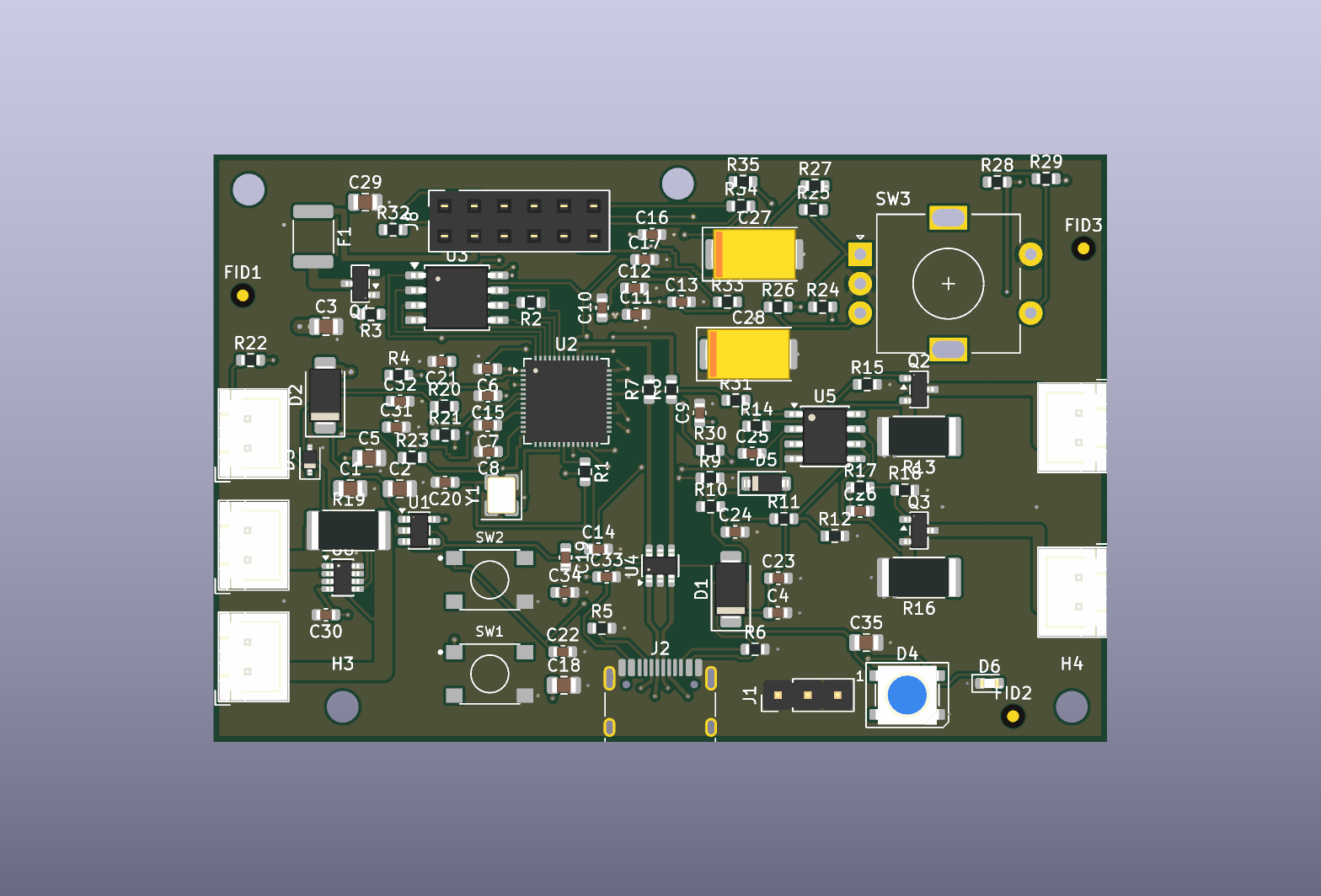
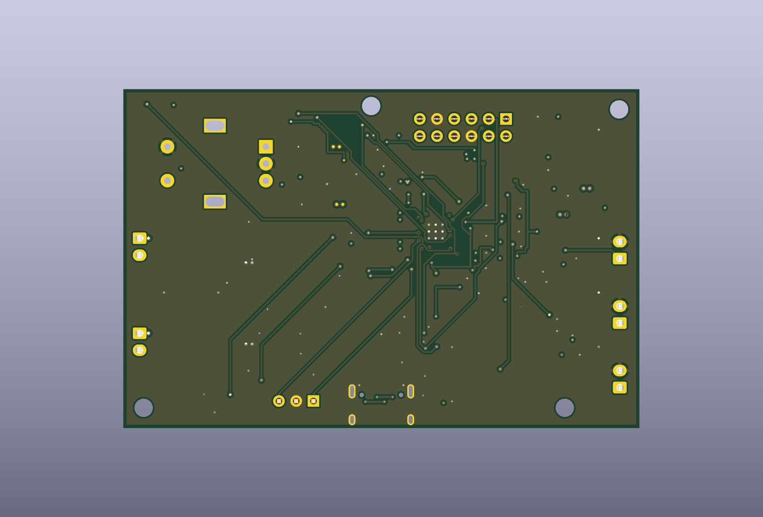
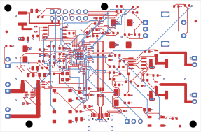
Signal routing, front copper red and back copper blue, planes hidden:
| Board | 76 x 50 mm, 4 layers |
| Schematic | ERC clean, 0 errors and 0 warnings |
| Layout | DRC clean, 0 violations and 0 unconnected, against JLCPCB's published 4-layer rules |
| Verification | 24 checks measured off the finished layout, no failures. Report |
| Firmware | builds clean under the Pico SDK |
| Fab outputs | Gerbers, drill, BOM, and placement files in fab/; the ready-to-upload set is fab/jlc/ |
| Path | Contents |
|---|---|
| hardware/skidl/ | schematic as code, the source of record |
| hardware/kicad/ | the board file and custom footprints |
| hardware/partlist.md | every part, the reasoning behind it, and where to order it |
| fab/ | Gerbers, Excellon drill, bom.csv, cpl.csv, renders |
| firmware/ | C firmware: I2C register file, flash safety logic, INA219, EC11, WS2812 |
| enclosure/ | 3D-printable pod holding the screen, this board, and the Pi 5 |
| docs/ | verification report, design rationale, and the Pi protocol |
| Qty | Value | Footprint | References |
|---|---|---|---|
| 18 | 100nF | C_0603_1608Metric | C6, C7, C10, C11, C12, C13, C14, C15, C21, C22, C23, C30, C31, C32, C33, C34 +2 |
| 7 | 1k | R_0603_1608Metric | R1, R10, R23, R25, R27, R29, R31 |
| 6 | 10k | R_0603_1608Metric | R3, R4, R22, R24, R26, R28 |
| 5 | 10uF | C_0805_2012Metric | C3, C5, C18, C29, C35 |
| 4 | 1uF | C_0603_1608Metric | C4, C16, C17, C24 |
| 4 | 330R | R_0603_1608Metric | R32, R33, R34, R35 |
| 4 | MountingHole_2.7mm_M2.5 | MountingHole_2.7mm_M2.5 | H1, H2, H3, H4 |
| 3 | 100k | R_0603_1608Metric | R9, R15, R18 |
| 3 | 27R | R_0603_1608Metric | R2, R7, R8 |
| 3 | Fiducial_1mm_Mask2mm | Fiducial_1mm_Mask2mm | FID1, FID2, FID3 |
| 2 | 0.5R 1% | R_2512_6332Metric | R13, R16 |
| 2 | 100R | R_0603_1608Metric | R14, R17 |
| 2 | 15pF | C_0603_1608Metric | C19, C20 |
| 2 | 1nF | C_0603_1608Metric | C25, C26 |
| 2 | 22uF | C_0805_2012Metric | C1, C2 |
| 2 | 4.7k | R_0603_1608Metric | R20, R21 |
| 2 | 470uF | CP_EIA-7343-30_AVX-N | C27, C28 |
| 2 | 5.1k | R_0603_1608Metric | R5, R6 |
| 2 | AO3400A | SOT-23 | Q2, Q3 |
| 2 | SS34 | D_SMA | D1, D2 |
| 2 | TACT | SW_TS-1187A_5.1x5.1mm | SW1, SW2 |
| 1 | 1.2k | R_0603_1608Metric | R12 |
| 1 | 10mR 2W 1% | R_2512_6332Metric | R19 |
| 1 | 12MHz | Crystal_SMD_3225-4Pin_3.2x2.5mm | Y1 |
| 1 | 1N4148W | D_SOD-123 | D5 |
| 1 | 470R | R_0603_1608Metric | R30 |
| 1 | 5.6k | R_0603_1608Metric | R11 |
| 1 | AO3401A | SOT-23 | Q1 |
| 1 | AP2112K-3.3 | SOT-23-5 | U1 |
| 1 | EC11 | RotaryEncoder_Alps_EC11E-Switch_Vertical_H20mm | SW3 |
| 1 | GREEN | LED_0603_1608Metric | D6 |
| 1 | INA219 | SOT-23-8 | U6 |
| 1 | LED1 | JST_XH_B2B-XH-A_1x02_P2.50mm_Vertical | J3 |
| 1 | LED2 | JST_XH_B2B-XH-A_1x02_P2.50mm_Vertical | J4 |
| 1 | LM358 | SOIC-8_3.9x4.9mm_P1.27mm | U5 |
| 1 | PESD5V0S1BA | D_SOD-323 | D3 |
| 1 | PTC 3A | Fuse_1812_4532Metric | F1 |
| 1 | Pi GPIO 1-12 | PinSocket_2x06_P2.54mm_Vertical | J8 |
| 1 | RP2040 | QFN-56-1EP_7x7mm_P0.4mm_EP3.2x3.2mm | U2 |
| 1 | SHUTTER | JST_XH_B2B-XH-A_1x02_P2.50mm_Vertical | J7 |
| 1 | SWD | PinHeader_1x03_P2.54mm_Vertical | J1 |
| 1 | USB-C | USB_C_Receptacle_HRO_TYPE-C-31-M-12 | J2 |
| 1 | USBLC6-2SC6 | SOT-23-6 | U4 |
| 1 | VBAT_IN | JST_XH_B2B-XH-A_1x02_P2.50mm_Vertical | J5 |
| 1 | VBAT_OUT | JST_XH_B2B-XH-A_1x02_P2.50mm_Vertical | J6 |
| 1 | W25Q128JVSIQ | SOIC-8_5.3x5.3mm_P1.27mm | U3 |
| 1 | WS2812B | LED_WS2812B_PLCC4_5.0x5.0mm_P3.2mm | D4 |
It measures 76 × 50 mm and has 4 copper layers, 1.6 mm thick.
105 parts, built around the RP2040, INA219AID, LM358 and W25Q128JVSIQ. The full list of its parts is on this page, with links to each part's symbol and footprint where PCBKit's library has them.
From the jadenrhee/wigglecam-controller repository on GitHub, at the commit this page was made from: the board is hardware/kicad/wigglecam.kicad_pcb. PCBKit opens the board in the browser, with nothing to install.
Its repository states no licence, so its author keeps all rights: ask jadenrhee before reusing the design.

lewipewi/leakwatch
A multi-channel leak sensor for equipment enclosures. Instead of reporting "wet / dry" like a normal leak probe, it measures how wet each enclosure is, on a separate channel per enclosure, and carries a second circuit…

maximus64/opendiag-hardware
OpenDIAG - Open Source OBD2 Interface (Hardware)


NuttyShell/NuttyBadge
NuttyBadge: A NuttyShell crafted multi-tool. Opensourced Hardawre and Software

EdgeCoil/wiegand-bridge
ESP32-S3 Wiegand reader bridge for Home Assistant: 4-layer board, BOM and ESPHome firmware.
