4 layers67.3 × 55.2 mm
Isno super v1.0
Isno-Open/OpenSuperRF
Design ouvert de la carte radio ISNO Super v1.0 (ESP32-S3, CC1101 433/868) pour firmwares radio comme OpenProfalux. CERN-OHL-S v2.
101 parts1CERN-OHL-S-2.0

 Isno-Open/OpenSuperRF1
Design ouvert de la carte radio ISNO Super v1.0 (ESP32-S3, CC1101 433/868) pour firmwares radio comme OpenProfalux. CERN-OHL-S v2.
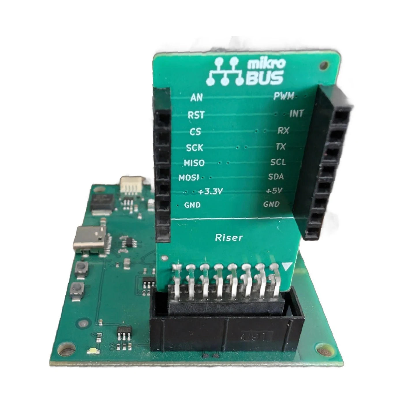
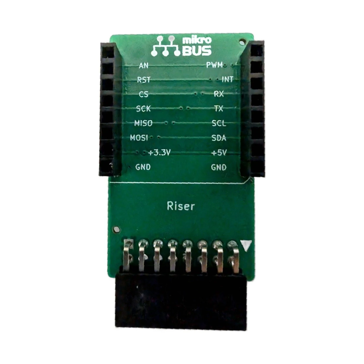
Mikrobus riser is an open-source printed circuit board by Isno-Open, from the Isno-Open/OpenSuperRF repository on GitHub, published under the CERN-OHL-S-2.0 licence. It is a 2-layer board of 25.4 × 48.4 mm with 3 parts on 15 nets, routed with 48 tracks and 15 vias.
It belongs with the radio and wireless and home automation and IoT boards and the ESP32 boards of this library.
(Version française : README.fr.md)
OpenSuperRF is the open design of the ISNO Super: a sub-GHz radio board built around an ESP32-S3, made to cleanly run open radio firmwares such as OpenProfalux (Profalux 868 MHz shutters in Home Assistant, no gateway).
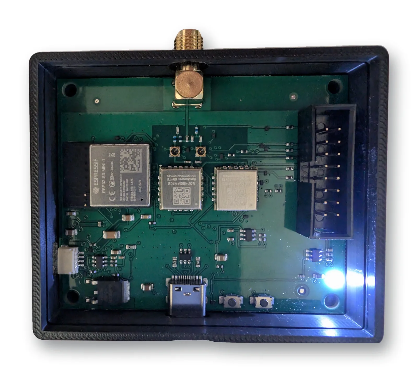
This is the v1.0 (EVT), the version that was manufactured, assembled and measured. It is published here as open hardware. The board sold as a pre-order is the v1.1, a refinement (see v1.0 open, v1.1 sold).
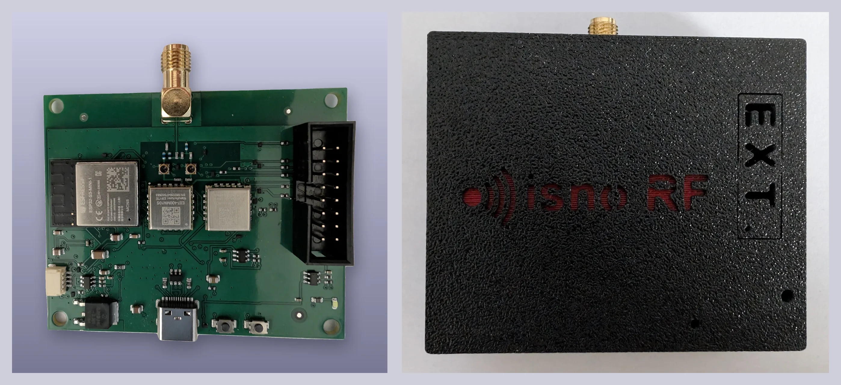
⚠️ Open points (v1.0 EVT). This prototype has known open points, including a J2 mikroBUS pinout that is destructive with a straight IDC cable. Read
KNOWN_ISSUES.mdbefore building.
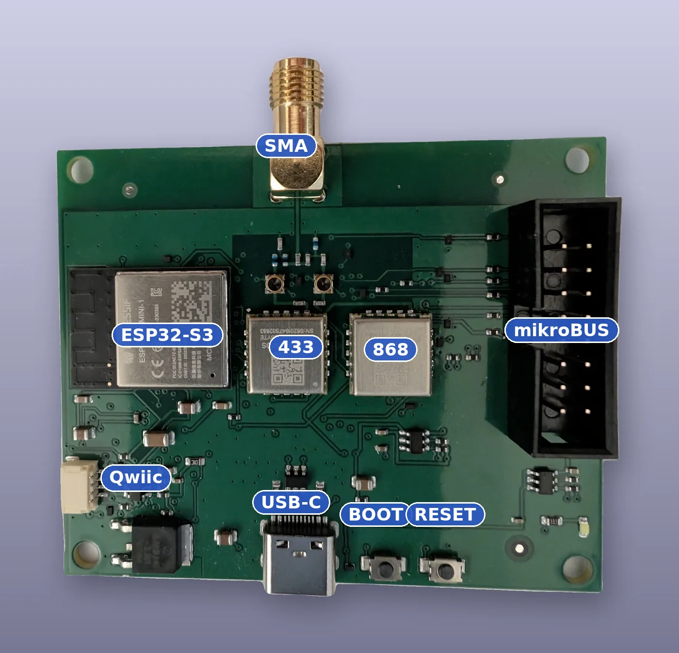
ISNO Super IoT HW REV 1.0.The Super is not tied to one firmware, it is a board for radio firmwares. It notably runs:
The v1.0 was measured: single, clean carriers, low noise floor, no spurious emissions over the observed window.
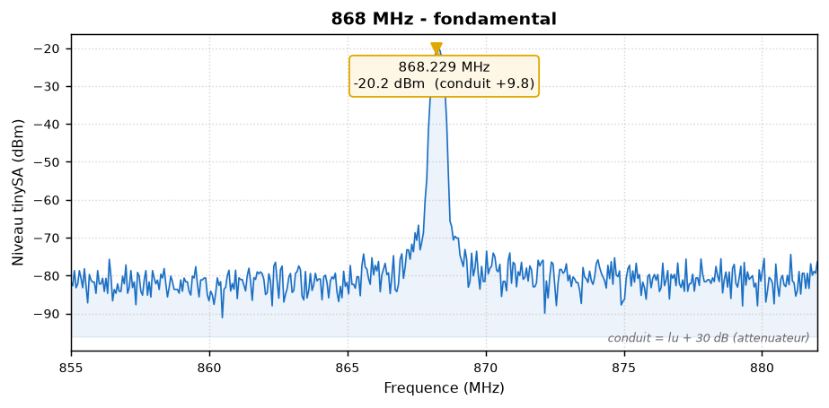
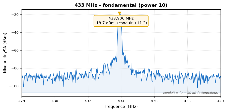
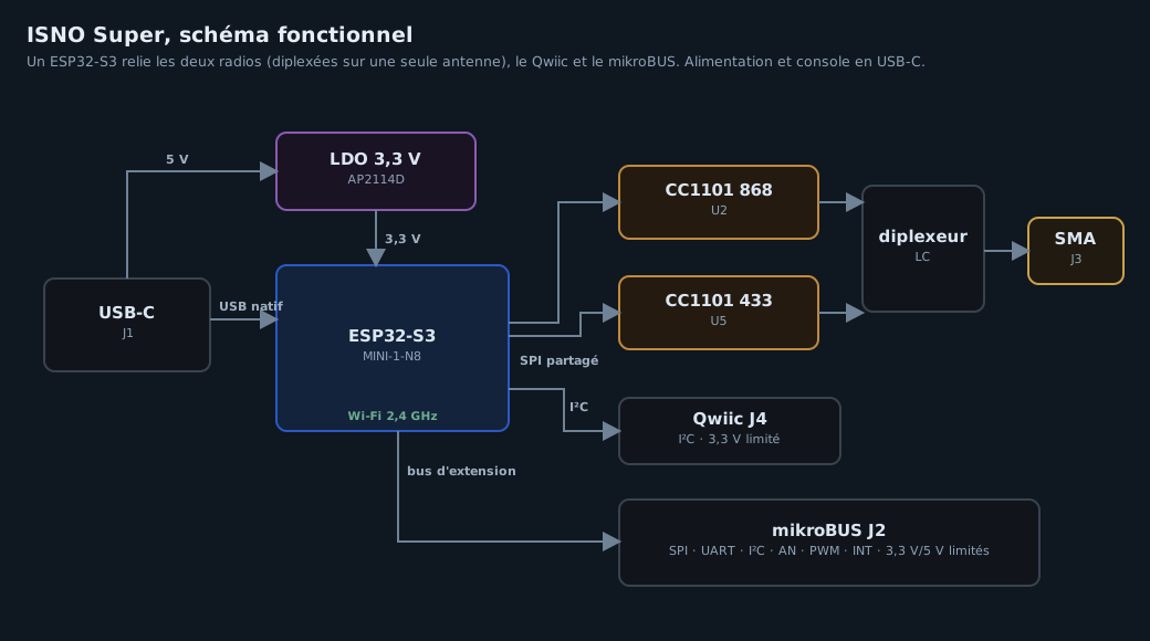
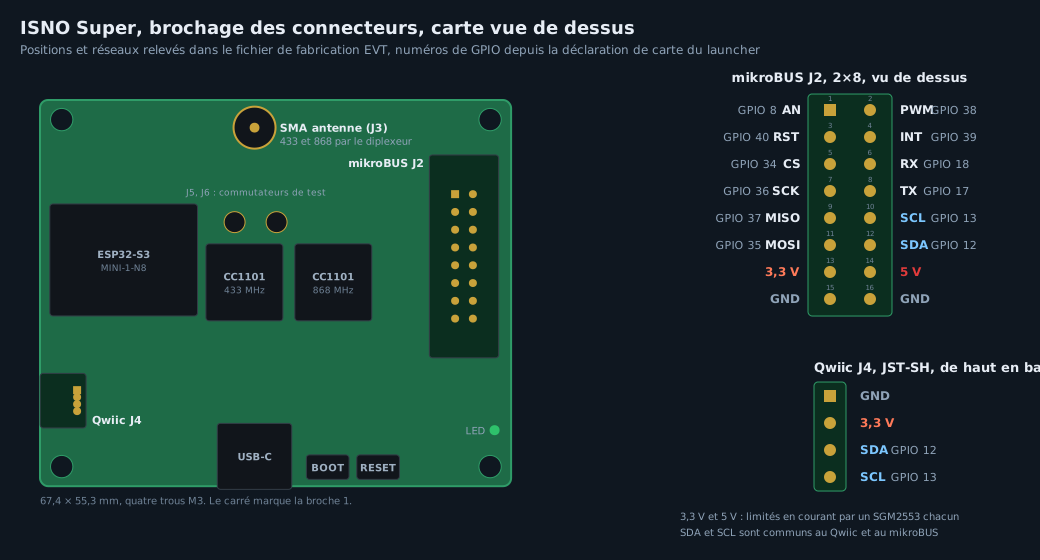
mikroBUS (left column): AN 8, RST 40, CS 34, SCK 36, MISO 37, MOSI 35, 3.3 V, GND. mikroBUS (right column): PWM 38, INT 39, RX 18, TX 17, SCL 13, SDA 12, 5 V, GND. Qwiic: GND, 3.3 V, SDA 12, SCL 13.
The full schematic is in docs/isno-super-v1.0-schematic.pdf.
A 3D-printable enclosure is provided in enclosures/ (boitier_super.stl). The board
also fits DIN-rail and IP65 enclosures.
Open here as well (produced, unchanged since). KiCad sources in hardware/accessories/.
To be clear, and honest:
DIY therefore stays fully possible and free; the v1.1 is the "ready and reliable" option for those who would rather not build it.
hardware/super/ : KiCad source of the Super v1.0 (schematic + PCB).hardware/accessories/ : KiCad source of the accessories (mikroBUS riser, adapter).hardware/OpenProfalux.pretty/, hardware/lib/ : custom footprints and symbols needed to open the
project in KiCad. The .pretty library keeps its historical name (the board started under the
OpenProfalux project); it is just the footprint library.fab/ : the manufactured EVT outputs (Gerbers, BOM, CPL, 3D render, EMC and thermal reports).enclosures/ : 3D-printable enclosure.docs/ : schematic PDF, BOM, production notes.images/ : photos, RF measurements, renders.Hardware: CERN-OHL-S v2 (see LICENSE). Associated firmwares: see their own repos.
| Qty | Value | Footprint | References |
|---|---|---|---|
| 1 | mikroBUS droite (PWM..GND) | Connector_PinSocket_2.54mm:PinSocket_1x08_P2.54mm_Vertical | J3 |
| 1 | mikroBUS gauche (AN..GND) | Connector_PinSocket_2.54mm:PinSocket_1x08_P2.54mm_Vertical | J2 |
| 1 | vers J2 Super (femelle 2x8 coudee) | Connector_PinSocket_2.54mm:PinSocket_2x08_P2.54mm_Horizontal | J1 |
It measures 25.4 × 48.4 mm and has 2 copper layers, 1.6 mm thick.
3 parts. The full list of its parts is on this page, with links to each part's symbol and footprint where PCBKit's library has them.
From the Isno-Open/OpenSuperRF repository on GitHub, at the commit this page was made from: the board is hardware/accessories/mikrobus-riser/mikrobus-riser.kicad_pcb and its schematic hardware/accessories/mikrobus-riser/mikrobus-riser.kicad_sch. PCBKit opens the board in the browser, with nothing to install.
Its repository publishes it under the CERN-OHL-S-2.0 licence: you may reuse it on that licence's terms (keep the author's notice, and for a copyleft licence share your changes alike).
Isno-Open/OpenSuperRF
Design ouvert de la carte radio ISNO Super v1.0 (ESP32-S3, CC1101 433/868) pour firmwares radio comme OpenProfalux. CERN-OHL-S v2.


hzeller/rpi-rgb-led-matrix
Controlling up to three chains of 64x64, 32x32, 16x32 or similar RGB LED displays using Raspberry Pi GPIO


atopile/atopile
Design circuit boards with code! ✨ Get software-like design reuse 🚀, validation, version control and collaboration in hardware; starting with electronics ⚡️


hackclub/sprig
🍃 Learn to code by making games in a JavaScript web-based game editor.