
2 layers65 × 63.5 mm

PCB and MCU programming project for eggs incubator temperature controller
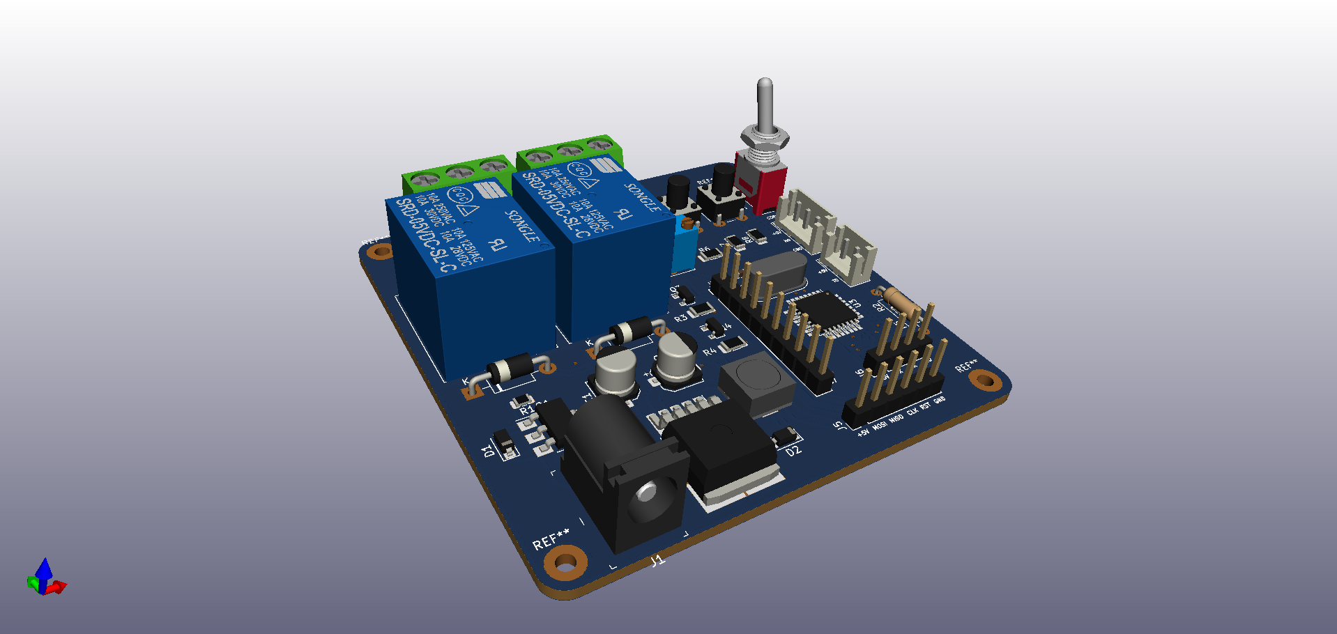
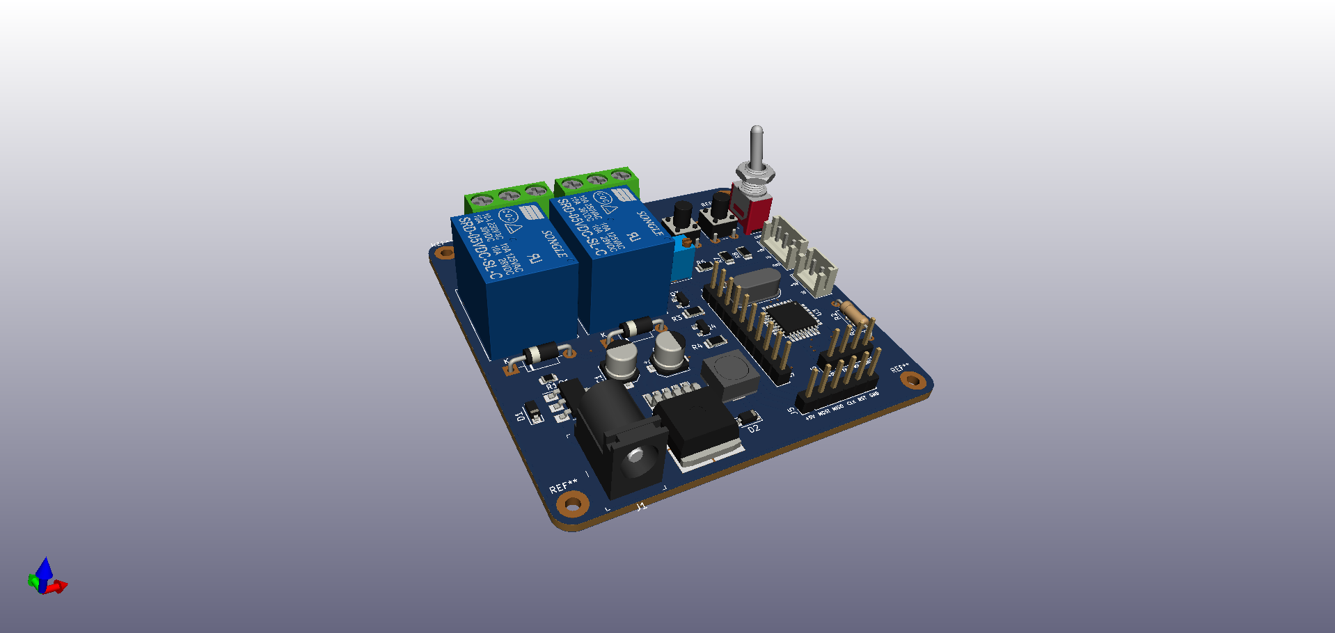
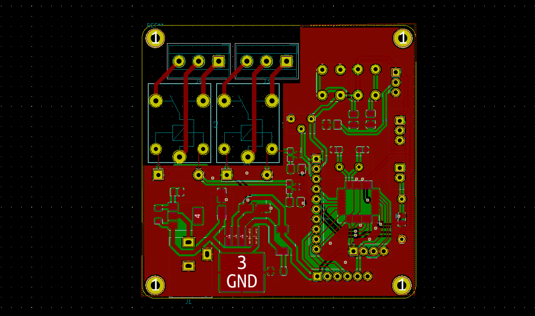
THERMOSTA is an open-source printed circuit board by infotronic218, from the infotronic218/EggsIncubatorController repository on GitHub. It is a 2-layer board of 69.1 × 69.1 mm with 41 parts on 35 nets, routed with 276 tracks and 19 vias.
It is built around the ATMEGA328P-AU, LM2596S-5.0 and BC547, with the BZT52B9V1-G and IPN70R360P7S among its other parts. Its parts include 8 resistors, 7 connectors, 5 switches, 4 capacitors and 4 diodes. It belongs with the AVR (ATmega, ATtiny) boards of this library.


This project is designed for humidity and temperature regalation for eggs incubation. The project used a Atmega328P, an NTC temperature sensor and a WHTM-02 Humidity and temperature sensor. The code is written in C programming language under AVR Studio Software.
| Qty | Value | Footprint | References |
|---|---|---|---|
| 3 | 10K | Resistor_SMD:R_1206_3216Metric | R6, R7, R8 |
| 2 | 1N4007 | Diode_THT:D_DO-41_SOD81_P10.16mm_Horizontal | D3, D4 |
| 2 | 22pF | Capacitor_SMD:C_0603_1608Metric | C3, C4 |
| 2 | BC547 | Package_TO_SOT_SMD:SOT-23 | Q3, Q4 |
| 2 | R | Resistor_SMD:R_1206_3216Metric | R3, R4 |
| 2 | SANYOU_SRD_Form_C | Relay_THT:Relay_SPDT_SANYOU_SRD_Series_Form_C | K1, K2 |
| 1 | 100K | Resistor_SMD:R_0805_2012Metric | R1 |
| 1 | 12V-INPUT | digikey-footprints:Barrel_Jack_5.5mmODx2.1mmID_PJ-102A | J1 |
| 1 | 1N5822 | Diode_SMD:D_SOD-123 | D2 |
| 1 | 220uF | Capacitor_SMD:CP_Elec_5x5.3 | C2 |
| 1 | 33uH | Inductor_SMD:L_6.3x6.3_H3 | L1 |
| 1 | 680uF | Capacitor_SMD:CP_Elec_5x5.3 | C1 |
| 1 | 8MHZ | Crystal:Crystal_HC49-4H_Vertical | Y1 |
| 1 | ATmega328P-AU | Package_QFP:TQFP-32_7x7mm_P0.8mm | U3 |
| 1 | B+ | Button_Switch_THT:SW_PUSH_6mm_H8mm | SW1 |
| 1 | B- | Button_Switch_THT:SW_PUSH_6mm_H8mm | SW3 |
| 1 | BZT52B9V1-G | Diode_SMD:D_SOD-123 | D1 |
| 1 | HEAT SWITCH | TerminalBlock_MetzConnect:TerminalBlock_MetzConnect_Type055_RT01503HDWU_1x03_P5.00mm_Horizontal | J3 |
| 1 | HUM SWITCH | TerminalBlock_MetzConnect:TerminalBlock_MetzConnect_Type055_RT01503HDWU_1x03_P5.00mm_Horizontal | J4 |
| 1 | IPN70R360P7S | Package_TO_SOT_SMD:SOT-223 | Q1 |
| 1 | LCD16L02 | Connector_PinHeader_2.54mm:PinHeader_1x10_P2.54mm_Vertical | J7 |
| 1 | LM2596S-5 | Package_TO_SOT_SMD:TO-263-5_TabPin3 | U1 |
| 1 | R | Resistor_SMD:R_0805_2012Metric | R2 |
| 1 | R | Resistor_THT:R_Axial_DIN0207_L6.3mm_D2.5mm_P10.16mm_Horizontal | R5 |
| 1 | R_POT | Potentiometer_THT:Potentiometer_Bourns_3266W_Vertical | RV1 |
| 1 | SPI | Connector_PinHeader_2.54mm:PinHeader_1x06_P2.54mm_Vertical | J5 |
| 1 | SW_Push_SPDT | Connector_PinSocket_2.54mm:PinSocket_1x03_P2.54mm_Vertical | SW2 |
| 1 | Thermistor_NTC | Connector_JST:JST_EH_B2B-EH-A_1x02_P2.50mm_Vertical | TH1 |
| 1 | UART | Connector_PinHeader_2.54mm:PinHeader_1x04_P2.54mm_Vertical | J6 |
| 1 | WHTM-02A | Connector_JST:JST_EH_B3B-EH-A_1x03_P2.50mm_Vertical | J2 |
The 37 most common of 41 parts.
It measures 69.1 × 69.1 mm and has 2 copper layers, 1.6 mm thick.
41 parts, built around the ATMEGA328P-AU, LM2596S-5.0, BC547 and BZT52B9V1-G. The full list of its parts is on this page, with links to each part's symbol and footprint where PCBKit's library has them.
From the infotronic218/EggsIncubatorController repository on GitHub, at the commit this page was made from: the board is KICAD/THERMOSTA.kicad_pcb. PCBKit opens the board in the browser, with nothing to install.
Its repository states no licence, so its author keeps all rights: ask infotronic218 before reusing the design.

MST-Robotics/TITAN-Electrical
This repository holds the electrical schematics and board layouts for the ROV (TITAN II) being built by the Missouri University of Science and Technology Underwater Robotics Design Team.


dark-Phoenix2077/wall-e
a custom smart rover with vision-assisted autonomous navigation and object tracking, built around a Raspberry Pi 3B+ and two fully custom PCB HATs.


Edgeberry/Edgeberry-Baseboard
Edgeberry Base Board for Raspberry Pi model B

SshgurkiratSingh/CCMS_PORTAL
A full-stack smart streetlight fleet management system with real-time monitoring, remote control, and analytics.