
2 layers101.6 × 55.9 mm
Clock
ifilot/sap-smd
Modular 8-bit computer built with TTL logic units to create a "Simple as Possible" system
72 parts2CERN-OHL-S-2.0

 ifilot/sap-smd2
Modular 8-bit computer built with TTL logic units to create a "Simple as Possible" system
Instruction decoder is an open-source printed circuit board by ifilot, from the ifilot/sap-smd repository on GitHub, published under the CERN-OHL-S-2.0 licence. It is a 2-layer board of 101.6 × 55.9 mm with 68 parts on 129 nets, routed with 1,563 tracks and 111 vias.
It is built around the 74HC238D, 74HC00D and 74HC161S. Its parts include 32 diodes, 11 capacitors, 10 ICs and 7 connectors. It belongs with the retro computing and games boards of this library.



This project showcases the design and construction of a modular 8-bit computer built with TTL logic units. The core principle behind the project is to create a "Simple as Possible" system, focusing on simplicity, modularity, and compactness.
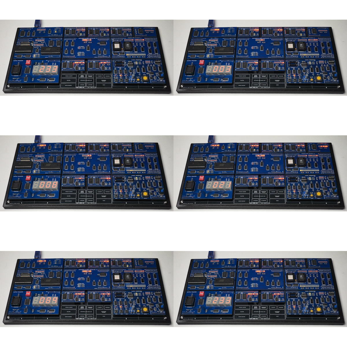
The project aims to:
SMD components offer several advantages:
This project is ideal for:
docs directory.Contributions to this project are welcome! If you have ideas for improvements, additional features, or alternative designs, feel free to fork the repository and submit a pull request.
| Qty | Value | Footprint | References |
|---|---|---|---|
| 10 | C | Capacitor_SMD:C_0805_2012Metric | C1, C2, C3, C4, C5, C6, C7, C8, C9, C10 |
| 6 | 74HC238 | Package_SO:SO-16_3.9x9.9mm_P1.27mm | U4, U5, U7, U8, U9, U10 |
| 4 | 220 | Resistor_SMD:R_Array_Convex_4x0603 | RN5, RN6, RN7, RN8 |
| 4 | 330 | Resistor_SMD:R_Array_Convex_4x0603 | RN1, RN2, RN3, RN4 |
| 2 | SST39SF040 | Package_LCC:PLCC-32_THT-Socket | U2, U6 |
| 1 | .1uF | Capacitor_THT:C_Disc_D5.0mm_W2.5mm_P5.00mm | C11 |
| 1 | 74HC00 | Package_SO:SO-14_3.9x8.65mm_P1.27mm | U3 |
| 1 | 74HC161 | Package_SO:SO-16_3.9x9.9mm_P1.27mm | U1 |
| 1 | CONTROL LINES | Connector_PinHeader_2.54mm:PinHeader_1x10_P2.54mm_Vertical | J7 |
| 1 | INSTRUCTION | Connector_PinHeader_2.54mm:PinHeader_1x10_P2.54mm_Vertical | J1 |
| 1 | OCLA0 | LED_SMD:LED_0805_2012Metric | D21 |
| 1 | OCLA1 | LED_SMD:LED_0805_2012Metric | D22 |
| 1 | OCLA2 | LED_SMD:LED_0805_2012Metric | D23 |
| 1 | OCLA3 | LED_SMD:LED_0805_2012Metric | D24 |
| 1 | OCLB0 | LED_SMD:LED_0805_2012Metric | D29 |
| 1 | OCLB1 | LED_SMD:LED_0805_2012Metric | D30 |
| 1 | OCLB2 | LED_SMD:LED_0805_2012Metric | D31 |
| 1 | OCLB3 | LED_SMD:LED_0805_2012Metric | D32 |
| 1 | ORTHOGONAL CONTROL LINES 1A | Connector_PinHeader_2.54mm:PinHeader_1x10_P2.54mm_Vertical | J3 |
| 1 | ORTHOGONAL CONTROL LINES 1B | Connector_PinHeader_2.54mm:PinHeader_1x10_P2.54mm_Vertical | J4 |
| 1 | ORTHOGONAL CONTROL LINES 2A | Connector_PinHeader_2.54mm:PinHeader_1x10_P2.54mm_Vertical | J5 |
| 1 | ORTHOGONAL CONTROL LINES 2B | Connector_PinHeader_2.54mm:PinHeader_1x10_P2.54mm_Vertical | J6 |
| 1 | PARALLEL CONTROL LINES | Connector_PinHeader_2.54mm:PinHeader_1x10_P2.54mm_Vertical | J2 |
| 1 | PCL0 | LED_SMD:LED_0805_2012Metric | D17 |
| 1 | PCL1 | LED_SMD:LED_0805_2012Metric | D18 |
| 1 | PCL2 | LED_SMD:LED_0805_2012Metric | D19 |
| 1 | PCL3 | LED_SMD:LED_0805_2012Metric | D20 |
| 1 | PCL4 | LED_SMD:LED_0805_2012Metric | D25 |
| 1 | PCL5 | LED_SMD:LED_0805_2012Metric | D26 |
| 1 | PCL6 | LED_SMD:LED_0805_2012Metric | D27 |
| 1 | PCL7 | LED_SMD:LED_0805_2012Metric | D28 |
| 1 | T0 | LED_SMD:LED_0805_2012Metric | D1 |
| 1 | T1 | LED_SMD:LED_0805_2012Metric | D2 |
| 1 | T10 | LED_SMD:LED_0805_2012Metric | D11 |
| 1 | T11 | LED_SMD:LED_0805_2012Metric | D12 |
| 1 | T12 | LED_SMD:LED_0805_2012Metric | D13 |
| 1 | T13 | LED_SMD:LED_0805_2012Metric | D14 |
| 1 | T14 | LED_SMD:LED_0805_2012Metric | D15 |
| 1 | T15 | LED_SMD:LED_0805_2012Metric | D16 |
| 1 | T2 | LED_SMD:LED_0805_2012Metric | D3 |
| 1 | T3 | LED_SMD:LED_0805_2012Metric | D4 |
| 1 | T4 | LED_SMD:LED_0805_2012Metric | D5 |
| 1 | T5 | LED_SMD:LED_0805_2012Metric | D6 |
| 1 | T6 | LED_SMD:LED_0805_2012Metric | D7 |
| 1 | T7 | LED_SMD:LED_0805_2012Metric | D8 |
| 1 | T8 | LED_SMD:LED_0805_2012Metric | D9 |
| 1 | T9 | LED_SMD:LED_0805_2012Metric | D10 |
It measures 101.6 × 55.9 mm and has 2 copper layers, 1.6 mm thick.
68 parts, built around the 74HC238D, 74HC00D and 74HC161S. The full list of its parts is on this page, with links to each part's symbol and footprint where PCBKit's library has them.
From the ifilot/sap-smd repository on GitHub, at the commit this page was made from: the board is pcb/components/instruction_decoder/instruction_decoder.kicad_pcb and its schematic pcb/backplates/bp-leanplate/bp-leanplate.kicad_sch. PCBKit opens the board in the browser, with nothing to install.
Its repository publishes it under the CERN-OHL-S-2.0 licence: you may reuse it on that licence's terms (keep the author's notice, and for a copyleft licence share your changes alike).
ifilot/sap-smd
Modular 8-bit computer built with TTL logic units to create a "Simple as Possible" system

ifilot/sap-smd
Modular 8-bit computer built with TTL logic units to create a "Simple as Possible" system

ifilot/sap-smd
Modular 8-bit computer built with TTL logic units to create a "Simple as Possible" system

ifilot/sap-smd
Modular 8-bit computer built with TTL logic units to create a "Simple as Possible" system

ifilot/sap-smd
Modular 8-bit computer built with TTL logic units to create a "Simple as Possible" system

ifilot/sap-smd
Modular 8-bit computer built with TTL logic units to create a "Simple as Possible" system

ifilot/sap-smd
Modular 8-bit computer built with TTL logic units to create a "Simple as Possible" system

ifilot/sap-smd
Modular 8-bit computer built with TTL logic units to create a "Simple as Possible" system

ifilot/sap-smd
Modular 8-bit computer built with TTL logic units to create a "Simple as Possible" system

ifilot/sap-smd
Modular 8-bit computer built with TTL logic units to create a "Simple as Possible" system


slu4coder/Minimal-64x4-Home-Computer
My DIY TTL home computer with VGA and PS/2 and 4x the processing power of a Commodore C64 or Apple II.

slu4coder/Minimal-UART-Computer-1-2
Legacy: Version 1 and 2 of my TTL-only CPU featuring UART I/O, an expansion port, 512KB SSD at up to 10MHz clock speed

slu4coder/Minimal-64-Home-Computer
Legacy: Full TTL-only home computer with VGA and PS/2 and twice the processing power of a Commodore 64

slu4coder/Minimal-UART-Computer-3
Version 3 of my educational DIY TTL computer built around a UART serial interface - now with blinkenlights!


