
4 layers85.1 × 100 mm

 ifilot/p2000t-sdcard3
SD-card cartridge for the P2000T
Internal sdcard interface is an open-source printed circuit board by ifilot, from the ifilot/p2000t-sdcard repository on GitHub. It is a 2-layer board of 219 × 88 mm with 79 parts on 156 nets, routed with 3,708 tracks and 177 vias.
It is built around the 74HC245D, 74HC00D and 74HC32D, with the 74HC138, 74HC273D and 74HC74D among its other parts. Its parts include 32 capacitors, 28 ICs, 7 resistors, 5 diodes and 4 connectors. It belongs with the retro computing and games and interfaces and adapters boards of this library.


[!TIP] Have questions or comments about the P2000T SD-card cartridge? Join the conversation and chat with the developers on our Discord server.
Check out the YouTube video below for a detailed review of the SD-card cartridge.

Perhaps the most elegant solution for loading CAS files into your P2000T or making backups of your tapes is via a cartridge that hosts an SD-card slot. Even the smallest SD-cards have enough capacity to store the complete P2000T tape archive. Reading from such an SD-card is non-trivial and requires both a hardware solution to interface with the I/O port of the P2000T as well as a software solution to navigate through the files hosted on a FAT32 partition. This repository contains the PCB for interfacing a P2000T with an SD-card and the necessary software routines to grab .CAS files from said SD card and load them into memory.
[!TIP] Documentation
- Detailed documentation included how-to procedures can be found here
- There is also a manual in Dutch
available.
Read the section "How it functions" to understand what each download file does.
[!WARNING] The files shown here cater specifically to PCB version 6 or later where the SD-card listens to I/O port 0x4X. Earlier version of the PCB are no longer actively maintained.
[!TIP]
To interface with the SD-card, an SD-card slot is connected to the I/O port of the P2000T. Interfacing with the SD-card proceeds via the SPI protocol which is encoded in hardware (in contrast to bit-banging the protocol in software). From the perspective of the P2000T, simple 1-byte instructions can be sent and retrieved from the SD-card. By sending specific commands, data is sent or retrieved from the SD-card.
While the SLOT2 cartridge (which hooks up to the I/O port of the P2000T) hosts
the circuitry to interface with the SD-card, a SLOT1 cartridge is required that
hosts the software. In order to run BASIC programs that are stored on the
SD-card as .CAS files, the regular BASIC environment and the required
routines to interface with the SD-card need to be present in memory. For this
reason, a modified version of the BASIC environment is used which upon boot will
load a launcher application from the ROM chip on the SLOT2 cartridge into main
memory. This launcher application allows the user to navigate the SD-card and
load BASIC programs into memory and run these. Detailed instructions on this
process are found here.
The launcher application needs to be placed on the ROM chip by means of a
flasher program. The flasher program is a different SLOT1 cartridge which can be
downloaded from the download section. The flasher program will
copy a LAUNCHER.BIN file from the root folder of the SD-card to the ROM chip
on the SLOT2 cartridge. This procedure is also used to update the launcher
application. Details on this process can be found here.
It is also possible to make copies of existing tapes to the SD-card. For this
purpose, a CASDUMP.PRG program is written. These special types of programs can
be loaded from the SD-card and executes via the launcher application. After
completion, one automatically returns to the launcher, allowing one to load one
of the freshly copied programs.
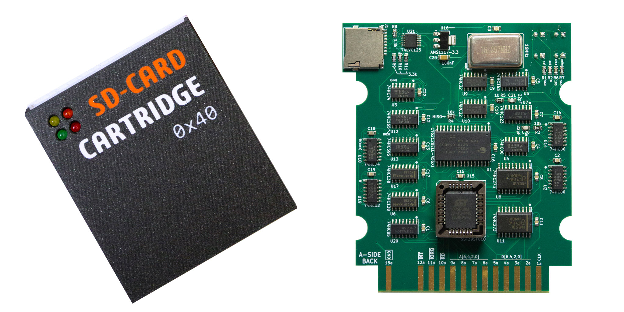
SLOT2 cartridge enclosure and populated PCB.
Screenshots of navigation and execution of .CAS files.
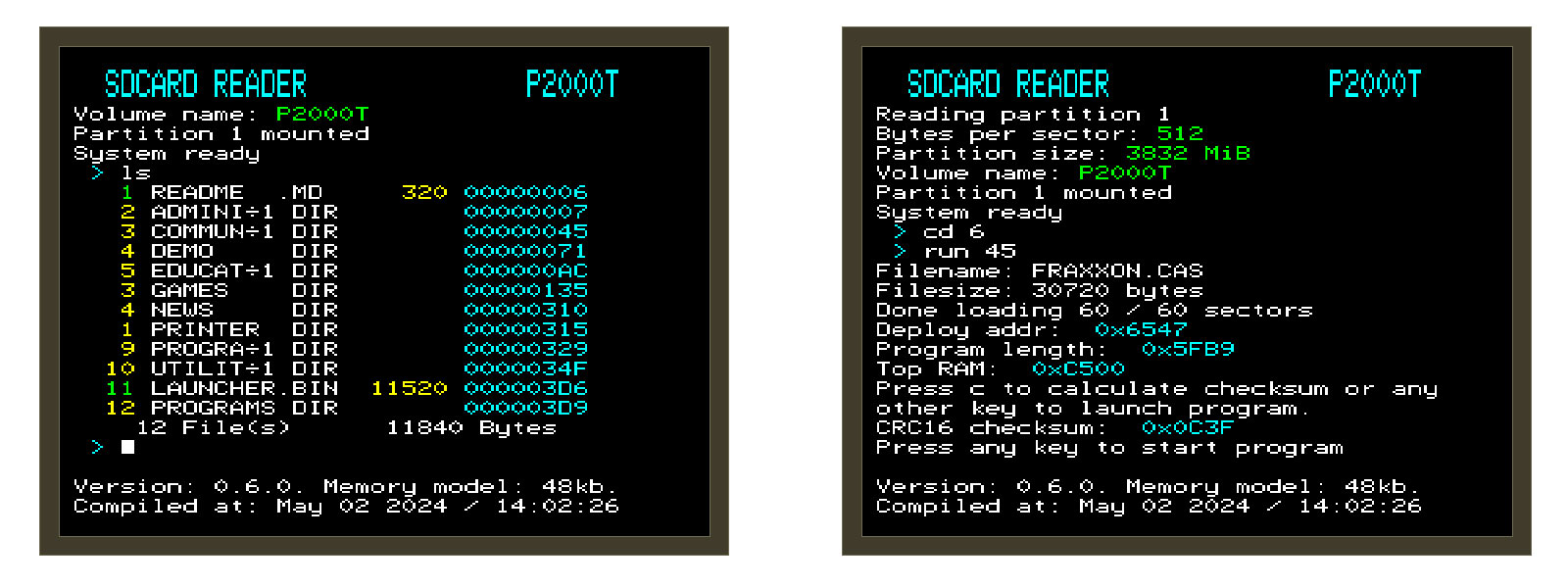
Upon booting into the LAUNCHER application, the user interfaces with the SD-card using a set of short commands. Below, the list of commands is provided
| Command | Description |
|---|---|
ls | List contents of current folder |
lscas | List contents of current folder, listing contents of CAS files |
cd <number> | Change directory |
run <number> | Run .CAS file |
hexdump <number> | Performs a 120-byte hexdump of a file |
fileinfo <number> | Provides location details of a file |
ledtest | Performs a quick test on the read/write LEDs |
stack | Show current position of the stack pointer |
dump<XXXX> | Perform a 120-byte hexdump of main memory starting at 0xXXXX |
romdump<XXXX> | Perform a 120-byte hexdump of cartridge ROM starting at 0xXXXX |
ramdump<XXXX> | Perform a 120-byte hexdump of cartridge RAM starting at 0xXXXX |
Note that <number> needs to replaced with the specific number of a file. Users
who are familiar with command line interfaces are probably used to specifying
filenames rather than numbers. This reason this approach was chosen is mainly
because it is simpler to program and furthermore a bit quicker to type.
Compilation is done using the z88dk Docker
by means of compile.sh. To compile the launcher, run
cd src
./compile launcher
and for the flasher utility
cd src
./compile flasherTo create your own SLOT2 cartridge, download the GERBER files from
here, put them in a .ZIP file and send
them to your favorite PCB print farm. The author of this repository mainly uses
JLCPCB, but plenty of alternatives are available. The
SLOT2 PCB has four layers. It is recommended to apply an ENIG (gold) coating and
chamfer the edge connector for facile insertion into the P2000T. After ordering,
one needs to either hand-solder the components (which can be tricky for the SMD
chips) or alternatively make use of an assembly service by which the PCB print
farm will solder these components for you.
The folder pcb/port2-sdcard-interface contains
port2-sdcard-interface_bom_bot.csv and port2-sdcard-interface-bottom-pos.csv
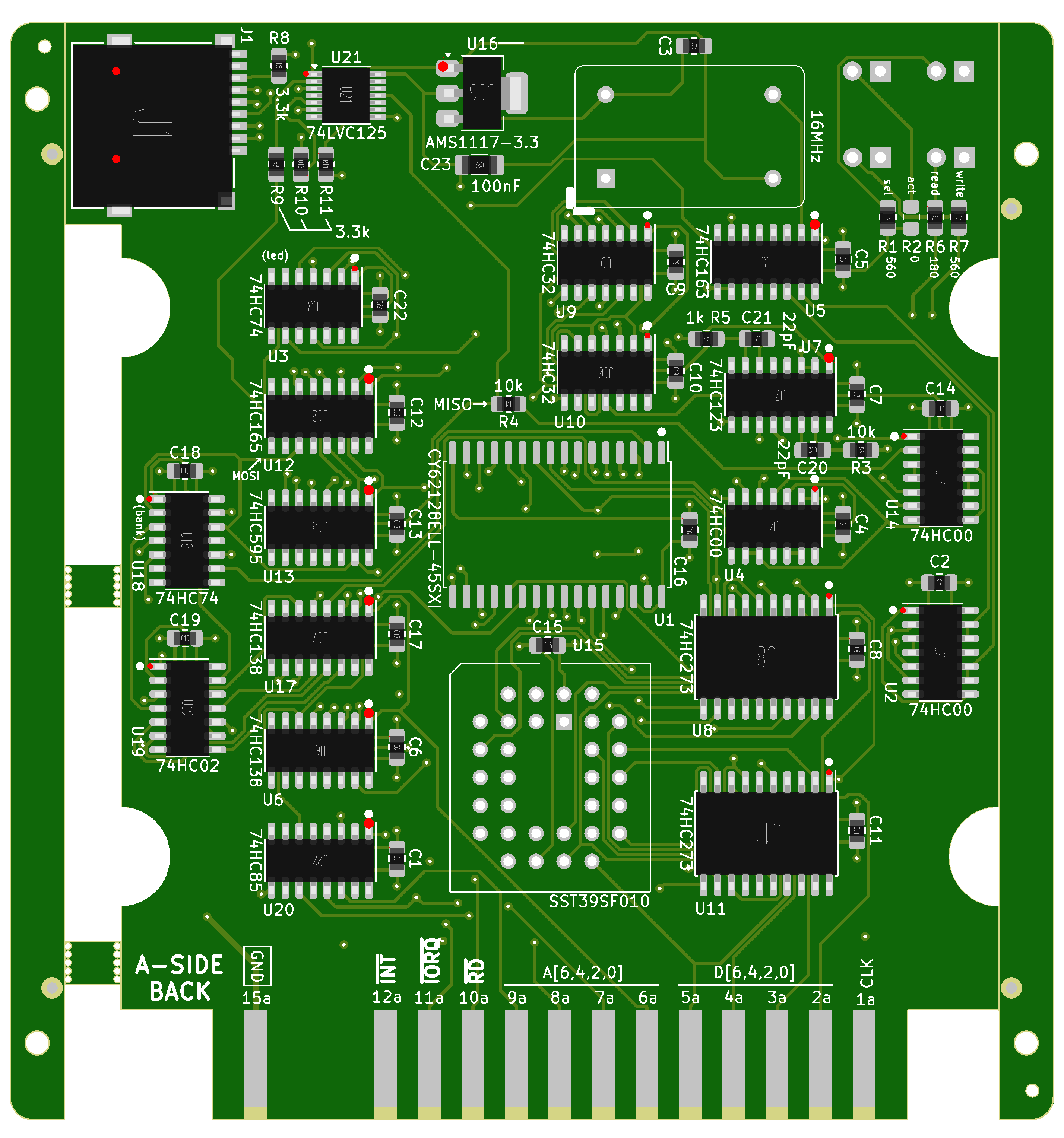
which can be used for the JLCPCB assembly service. An example of the part
placement can be found in the image below. At the time of writing, two
components were unavailable, being the memory chip 62128 and a 0 ohm resistor,
which is the reason that these two parts are missing. Note that all through-hole
parts, e.g. LEDs, oscillator and PLCC32 socket, have to be hand-soldered in.
It is also possible to order a cartridge (typically there are always a few
of them in stock). If you are interested, feel free to contact the author of
this repository at ivo at ivofilot dot nl to discuss pricing and shipping.
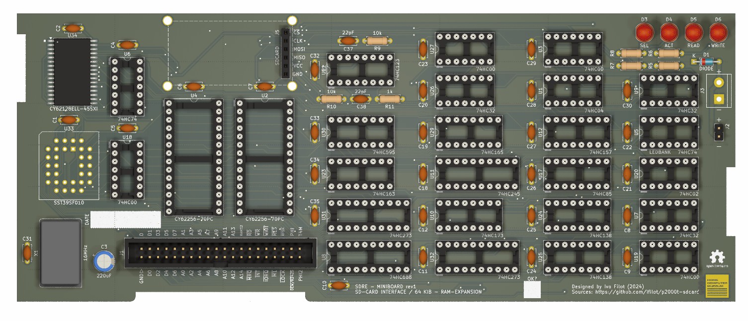
This project also includes an internal SD-card board designed to mount on top of the main baseboard inside the P2000T. In addition to the SD-card reader functionality, the board also provides 64 KiB of additional memory, making it an all-in-one solution.
To install this board, you will need two custom brackets. You can find the necessary bracket files here.
The way that the SD-card is formatted is critical. The SD-card needs be formatted using a MBR/FAT32 partition. Often, directly formatting the SD-card via Windows Explorer or similar works well, but sometimes a more rigorous procedure is needed, which is explained below.
WINDOWS + R and run CMD.diskpart.list disk followed by select disk <NR> where <NR> corresponds to
your SD-card.clean. You get a response with DiskPart succeeded in cleaning the disk..list volume, followed by select volume <ID> where <ID> corresponds
to your SD-card drive.convert mbr. You should get the response DiskPart successfully converted the selected disk to MBR format..create partition primary. The response should be DiskPart succeeded in creating the specified partition..format fs=fat32 quick label="P2000T", after which the
response is DiskPart successfully formatted the volume..Your SD-card should now be ready to work in the SD-cartridge. Of course, you still need to copy files to it in order to load something of it.
| Qty | Value | Footprint | References |
|---|---|---|---|
| 29 | 0.1uF | Capacitor_THT:C_Disc_D5.0mm_W2.5mm_P5.00mm | C1, C2, C10, C11, C12, C18, C19, C20, C21, C22, C23, C24, C25, C26, C27, C28 +13 |
| 4 | 74HC00 | Package_DIP:DIP-14_W7.62mm_Socket | U3, U18, U19, U27 |
| 3 | 74HC32 | Package_DIP:DIP-14_W7.62mm_Socket | U7, U9, U26 |
| 2 | 10k | Resistor_THT:R_Axial_DIN0207_L6.3mm_D2.5mm_P7.62mm_Horizontal | R9, R10 |
| 2 | 22pF | Capacitor_THT:C_Disc_D5.0mm_W2.5mm_P5.00mm | C37, C38 |
| 2 | 560 | Resistor_THT:R_Axial_DIN0207_L6.3mm_D2.5mm_P7.62mm_Horizontal | R6, R7 |
| 2 | 74HC138 | Package_DIP:DIP-16_W7.62mm_Socket | U24, U25 |
| 2 | 74HC273 | Package_DIP:DIP-20_W7.62mm_Socket | U31, U32 |
| 2 | 74HC74 | Package_DIP:DIP-14_W7.62mm_Socket | U5, U6 |
| 2 | CY62256-70PC | Package_DIP:DIP-28_W15.24mm_Socket | U2, U4 |
| 1 | CY62128ELL-45SXI | Package_SO:SSOP-32_11.305x20.495mm_P1.27mm | U34 |
| 1 | 0 | Resistor_THT:R_Axial_DIN0207_L6.3mm_D2.5mm_P7.62mm_Horizontal | R8 |
| 1 | 16MHz | Oscillator:Oscillator_DIP-14 | X1 |
| 1 | 180 | Resistor_THT:R_Axial_DIN0207_L6.3mm_D2.5mm_P7.62mm_Horizontal | R5 |
| 1 | 1k | Resistor_THT:R_Axial_DIN0207_L6.3mm_D2.5mm_P7.62mm_Horizontal | R11 |
| 1 | 220uF | Capacitor_THT:CP_Radial_D6.3mm_P2.50mm | C3 |
| 1 | 74HC02 | Package_DIP:DIP-14_W7.62mm_Socket | U20 |
| 1 | 74HC04 | Package_DIP:DIP-14_W7.62mm_Socket | U1 |
| 1 | 74HC123 | Package_DIP:DIP-16_W7.62mm_Socket | U21 |
| 1 | 74HC157 | Package_DIP:DIP-16_W7.62mm_Socket | U12 |
| 1 | 74HC163 | Package_DIP:DIP-16_W7.62mm_Socket | U23 |
| 1 | 74HC165 | Package_DIP:DIP-16_W7.62mm_Socket | U29 |
| 1 | 74HC173 | Package_DIP:DIP-16_W7.62mm_Socket | U10 |
| 1 | 74HC245 | Package_DIP:DIP-20_W7.62mm_Socket | U11 |
| 1 | 74HC595 | Package_DIP:DIP-16_W7.62mm_Socket | U30 |
| 1 | 74HC688 | Package_DIP:DIP-20_W7.62mm_Socket | U8 |
| 1 | 74HC85 | Package_DIP:DIP-16_W7.62mm_Socket | U17 |
| 1 | ACT | LED_THT:LED_D5.0mm | D4 |
| 1 | DIODE | Diode_THT:D_DO-35_SOD27_P7.62mm_Horizontal | D1 |
| 1 | EXPANSION BOARD | Connector_IDC:IDC-Header_2x20_P2.54mm_Vertical | J1 |
| 1 | LOGO | components:hcm_logo | G001 |
| 1 | POWER | Connector_PinHeader_2.54mm:PinHeader_1x02_P2.54mm_Vertical | J2 |
| 1 | READ | LED_THT:LED_D5.0mm | D5 |
| 1 | SDCARD | sdcard-holder:sdcard-socket | J5 |
| 1 | SEL | LED_THT:LED_D5.0mm | D3 |
| 1 | SST39SF010 | Package_LCC:PLCC-32_THT-Socket | U33 |
| 1 | TERMINAL | TerminalBlock:TerminalBlock_bornier-2_P5.08mm | J3 |
| 1 | WRITE | LED_THT:LED_D5.0mm | D6 |
The 78 most common of 79 parts.


nailed-barnacle/Cisc-8-ttl-processor
A cut-down version of the 8080 processor using HCTTL and including a discrete ALU and instruction decoder


KITTY-6502/hardware
the KITTY is a 65c02 homebrew kit microcomputer designed around text mode graphics and cartridge media. It is fully open source, and uses exclusively in-production parts.
It measures 219 × 88 mm and has 2 copper layers, 1.6 mm thick.
79 parts, built around the 74HC245D, 74HC00D, 74HC32D and 74HC138. The full list of its parts is on this page, with links to each part's symbol and footprint where PCBKit's library has them.
From the ifilot/p2000t-sdcard repository on GitHub, at the commit this page was made from: the board is pcb/internal-sdcard-interface/internal-sdcard-interface.kicad_pcb and its schematic pcb/internal-sdcard-interface/internal-sdcard-interface.kicad_sch. PCBKit opens the board in the browser, with nothing to install.
Its repository states no licence, so its author keeps all rights: ask ifilot before reusing the design.