4 layers55 × 72.1 mm
Main unit
HyFiVeUser/HyFiVe
For this use case we developed a very flexible autonomous measuring system, which can be deployed on fishing gear to collect data in an affordable and scalable way.
132 partsCC-BY-SA-4.0

 HyFiVeUser/HyFiVe
For this use case we developed a very flexible autonomous measuring system, which can be deployed on fishing gear to collect data in an affordable and scalable way.
I2C Adapter is an open-source printed circuit board by HyFiVeUser, from the HyFiVeUser/HyFiVe repository on GitHub, published under the CC-BY-SA-4.0 licence. It is a 4-layer board of 74.2 × 32.2 mm with 32 parts on 55 nets, routed with 310 tracks and 62 vias.
It is built around the TXS0102DCU, 9HT11-32.768KDZF-T and A6H-8101, with the ESQ-104-14-G-D, RCLAMP0582B and SKRKAEE020 among its other parts. Its parts include 9 capacitors, 8 resistors, 5 crystals, 3 switches and 2 ICs. It belongs with the interfaces and adapters boards and the MSP430 boards of this library.



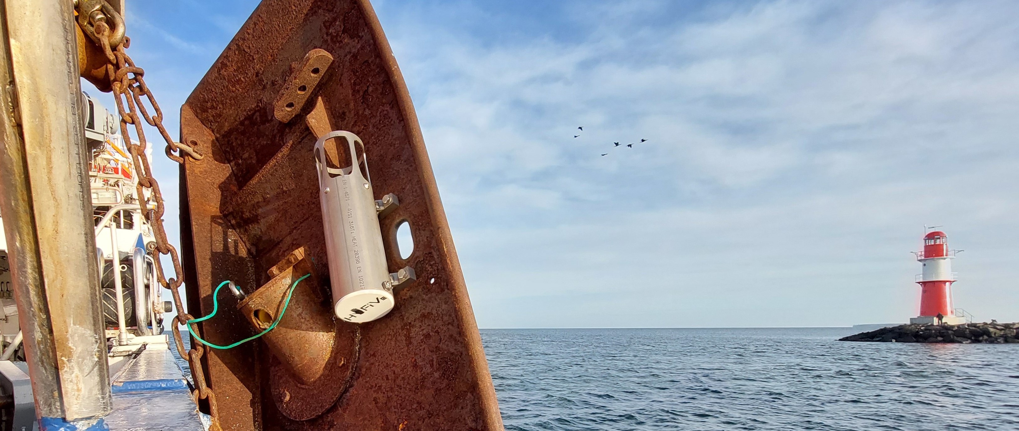
Whether for modelling climate change or for our understanding of fish stocks – ocean data is essential for many disciplines. Usually, this data is collected by research vessels, which are cost-intensive and thus limited in space and time. To increase data resolution ‘vessels of opportunity’ can be a scalable alternative. In this concept vessels are used as measuring platforms, that are originally financed for a non-scientific purpose. Especially fishing vessels are of interest as they deploy gear in deep water and so make the whole water column accessible for an attached measuring system.
For this use case we developed a very flexible autonomous measuring system, which can be deployed on fishing gear to collect data in an affordable and scalable way. This was done within the project ‘Hydrography on Fishing Vessels - HyFiVe’
This measuring system essentially consists of three components:
As overarching topic, bi-directional communication between these components is described separately.
The HyFiVe system offers many advantages:
The system was developed in an agile method, so prototypes were built from an early stage on and tested continuously. Till the end of the first project in Sept 2024 the system was deployed on over ten vessels, among them research vessels, trawl fishing vessels, gill net fishing vessels and recreational vessels like sailing boats.
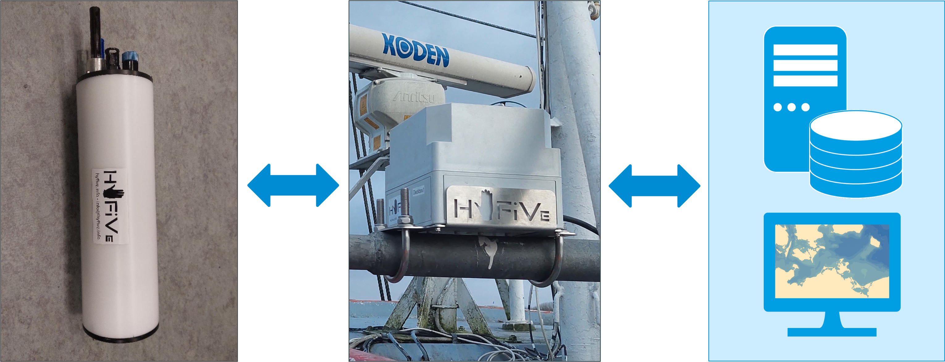
Figure 1: [blocked] Logger, deck box and server - the three components of the HyFiVe measuring system
This documentation is aimed to enable you to build an own HyFiVe system and therefore contains detailed informations about all parts. If you are interested in building a system and lack information, please get in contact with us.
Disclaimer: We do not guarantee that the description is accurate throughout or complete. All your work is done at your own risk. Please comply with all necessary and legal safety precautions, especially when high voltage is involved, to avoid damage to yourself, others and the hardware.
The three components have separate folders with hardware, software and specific information including READMEs which can be followed step by step. The READMEs contain
HyFiVe is an open-source project consisting of software, hardware, and documentation components. Each part of this project is licensed under a different copyleft license to ensure it remains free and open:
The HyFiVe logo is not published under above licenses and not free to use.
An overview of the legal implications resulting from this licenses can be fund under https://joinup.ec.europa.eu/collection/eupl/solution/joinup-licensing-assistant/jla-find-and-compare-software-licenses.
This project was funded by the German Federal Ministry of Food and Agriculture.

| Qty | Value | Footprint | References |
|---|---|---|---|
| 4 | MountingHole | MountingHole:MountingHole_2.7mm_M2.5 | H201, H202, H203, H204 |
| 2 | 100nF | Capacitor_SMD:C_0603_1608Metric_Pad1.08x0.95mm_HandSolder | C205, C301 |
| 2 | 10k NB | Resistor_SMD:R_0603_1608Metric_Pad0.98x0.95mm_HandSolder | R203, R204 |
| 2 | 10k n.b. | Resistor_SMD:R_0603_1608Metric_Pad0.98x0.95mm_HandSolder | R301, R304 |
| 2 | 20pF | Capacitor_SMD:C_0603_1608Metric_Pad1.08x0.95mm_HandSolder | C203, C204 |
| 1 | 0R | Resistor_SMD:R_0603_1608Metric_Pad0.98x0.95mm_HandSolder | R302 |
| 1 | 0R n.b. | Resistor_SMD:R_0603_1608Metric_Pad0.98x0.95mm_HandSolder | R303 |
| 1 | 100uF | Capacitor_SMD:C_0805_2012Metric_Pad1.18x1.45mm_HandSolder | C1 |
| 1 | 1nF | Capacitor_SMD:C_0603_1608Metric_Pad1.08x0.95mm_HandSolder | C201 |
| 1 | 1µF | Capacitor_SMD:C_0603_1608Metric_Pad1.08x0.95mm_HandSolder | C206 |
| 1 | 1µF, <200m ESR | Capacitor_SMD:C_0603_1608Metric_Pad1.08x0.95mm_HandSolder | C202 |
| 1 | 330 | Resistor_SMD:R_0603_1608Metric_Pad0.98x0.95mm_HandSolder | R202 |
| 1 | 4,7µF | Capacitor_SMD:C_0603_1608Metric_Pad1.08x0.95mm_HandSolder | C207 |
| 1 | 47k | Resistor_SMD:R_0603_1608Metric_Pad0.98x0.95mm_HandSolder | R201 |
| 1 | 9HT11-32.768KDZF-T | Crystal:Crystal_SMD_TXC_9HT11-2Pin_2.0x1.2mm_HandSoldering | Y201 |
| 1 | A6H-8101 | Button_Switch_SMD:SW_DIP_SPSTx08_Slide_Omron_A6H-8101_W6.15mm_P1.27mm | SW202 |
| 1 | Conn_01x03 | Connector_PinHeader_2.54mm:PinHeader_1x03_P2.54mm_Vertical | X203 |
| 1 | Conn_02x03_Counter_Clockwise | Connector_PinHeader_2.54mm:PinHeader_2x03_P2.54mm_Vertical | X202 |
| 1 | ESQ-104-14-G-D | Connector_PinSocket_2.54mm:PinSocket_2x04_P2.54mm_Vertical | X201 |
| 1 | MSP430FR2673 | Package_DFN_QFN:VQFN-32-1EP_5x5mm_P0.5mm_EP3.5x3.5mm | IC201 |
| 1 | Molex Nano-Fit 103514-1*114 | Connector_Molex:Molex_Nano-Fit_105314-xx14_2x07_P2.50mm_Horizontal | X301 |
| 1 | RCLAMP0582B | Package_TO_SOT_SMD:SOT-416 | D301 |
| 1 | SKRKAEE020 | Button_Switch_SMD:SW_Push_SPST_NO_Alps_SKRK | SW201 |
| 1 | SSM3K127TU | Package_TO_SOT_SMD:SOT-23 | K301 |
| 1 | TXS0102DCU | Package_SO:VSSOP-8_2.3x2mm_P0.5mm | IC301 |
It measures 74.2 × 32.2 mm and has 4 copper layers, 4.69 mm thick.
32 parts, built around the TXS0102DCU, 9HT11-32.768KDZF-T, A6H-8101 and ESQ-104-14-G-D. The full list of its parts is on this page, with links to each part's symbol and footprint where PCBKit's library has them.
From the HyFiVeUser/HyFiVe repository on GitHub, at the commit this page was made from: the board is 01_Logger/02_Modular_Logger/01_Electronics/02_Adapter/I2C-Adapter/I2C-Adapter.kicad_pcb and its schematic 01_Logger/01_Basic_Logger/01_Electronics/KellerConnector/KellerConnector.kicad_sch. PCBKit opens the board in the browser, with nothing to install.
Its repository publishes it under the CC-BY-SA-4.0 licence: you may reuse it on that licence's terms (keep the author's notice, and for a copyleft licence share your changes alike).
HyFiVeUser/HyFiVe
For this use case we developed a very flexible autonomous measuring system, which can be deployed on fishing gear to collect data in an affordable and scalable way.

HyFiVeUser/HyFiVe
For this use case we developed a very flexible autonomous measuring system, which can be deployed on fishing gear to collect data in an affordable and scalable way.

HyFiVeUser/HyFiVe
For this use case we developed a very flexible autonomous measuring system, which can be deployed on fishing gear to collect data in an affordable and scalable way.

HyFiVeUser/HyFiVe
For this use case we developed a very flexible autonomous measuring system, which can be deployed on fishing gear to collect data in an affordable and scalable way.

HyFiVeUser/HyFiVe
For this use case we developed a very flexible autonomous measuring system, which can be deployed on fishing gear to collect data in an affordable and scalable way.

HyFiVeUser/HyFiVe
For this use case we developed a very flexible autonomous measuring system, which can be deployed on fishing gear to collect data in an affordable and scalable way.

HyFiVeUser/HyFiVe
For this use case we developed a very flexible autonomous measuring system, which can be deployed on fishing gear to collect data in an affordable and scalable way.

Ch-Schilling/NavHat
The board is designed using KiCad. For more details, see the corresponding documentation.


Conor-Dunlop/FYP_datalogger
render of the datalogger with power board (yes i know it need routed)


o7-machinehum/phantomdrive
Seemingly normal USB drive with a hidden security feature


alvarop/swd2usbc
Have you ever wanted to debug your device over USB-C? Sometimes there's not enough room for a JTAG/SWD connector, or even Tag-Connect pads!