
4 layers100 × 90 mm

OAS — Open Ambient Sensor: DIY multi-sensor indoor environmental monitor (CO2, PM, VOC/NOx, temperature/humidity, mmWave presence) on ESP32-C6 with ESPHome / Home Assistant integration
Oas is an open-source printed circuit board by hubertciebiada, from the hubertciebiada/open-ambient-sensor repository on GitHub, published under the GPL-3.0 licence. It is a 2-layer board of 89.2 × 103.5 mm with 64 parts on 45 nets, routed with 373 tracks and 37 vias.
It is built around the LM2596S-5.0, TPS62933DRL and SK6812SIDE-A, with the 1812L075/33DR, 220UF 10V 5*7 and AO3401A among its other parts. Its parts include 23 capacitors, 10 diodes, 8 connectors, 7 resistors and 2 ICs. It belongs with the home automation and IoT and sensors and measurement boards and the ESP32 and RISC-V boards of this library.


DIY multi-sensor environmental monitor for indoor spaces.
Measures air quality and presence; mounts on a standard wall-recessed electrical box; runs ESPHome and integrates natively with Home Assistant.





https://github.com/user-attachments/assets/d60150c3-3ed5-4fff-b437-b9b54c48e413
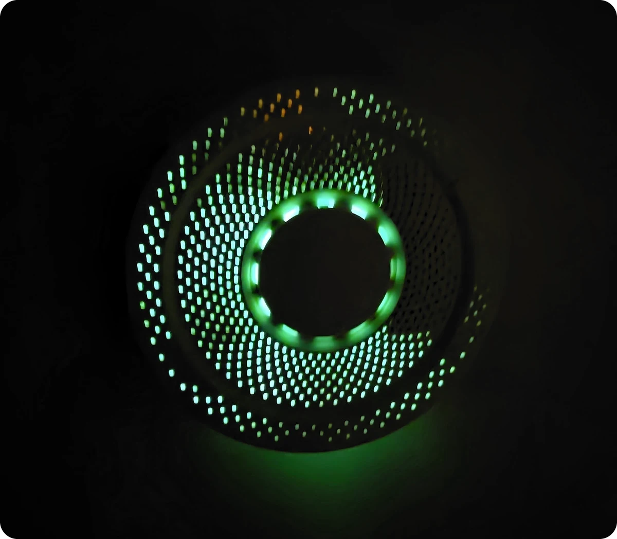
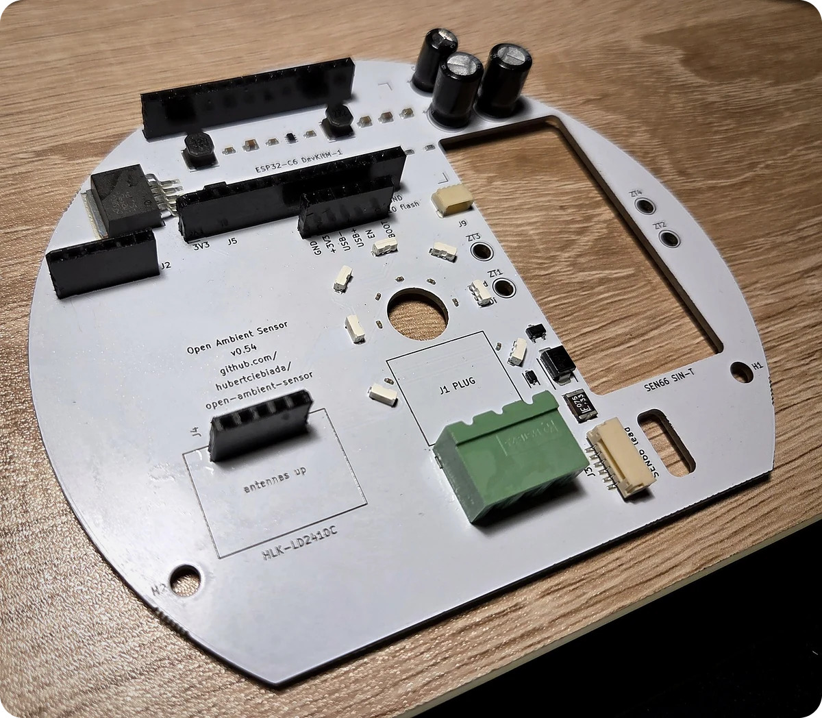
v0.54 — manufactured, bench-validated and in use. Boards of this revision were fabricated and SMT-assembled at JLCPCB, brought up on the bench with a repeatable per-unit check, and run in a multi-unit deployment as the sensor input for Home Assistant HVAC automations. Working on the delivered hardware: the 24 V power chain, the Sensirion SEN66 (CO₂ / PM / VOC / NOx / T / RH, with Sensirion's STAR temperature compensation running inside the module), the HLK-LD2410C presence radar including stillness detection, the LED ring, Wi-Fi / OTA / native Home Assistant API, the Bluetooth proxy and the on-device web dashboard. The firmware reports project_version: v0.54, matching the version printed on the silkscreen. The design is fully script-generated and verified: build.py 35/35 stages PASS, DRC 0 violations / 0 unconnected, JLCPCB DFM 0 Danger on both the bare-board and assembly checks. The production files for this revision are attached to the GitHub release. See CLAUDE.md for the design rationale, hard constraints and the lessons learned along the way.
Yes — this revision has been built and works. What to know before ordering:
hardware/output/jlcpcb/ holds the gerber + drill bundle, the BOM and the CPL files for JLCPCB SMT assembly (also attached to the GitHub release); they are regenerated and verified by the 35-stage pipeline on every build. Follow the ordering workflow in CLAUDE.md — in particular the pre-payment Assembly Order cross-check, which has caught wrong-part substitutions more than once.firmware/README.md.Known limitations (findings on the built units):
firmware/esphome/packages/presence.yaml.firmware/esphome/HARDWARE-COMPAT-v0.51.md; v0.54 boards run the firmware defaults.A consolidated step-by-step build guide is not written yet; open work is tracked in the TODO list in CLAUDE.md.
The open-source DIY space offers many indoor-air-quality projects. Most optimise aggressively for cost. OAS holds two priorities non-negotiable, even when the trade-off is a higher per-unit BOM than the cheapest alternatives:
Both compromises (cheap-but-inaccurate, accurate-but-ugly) are rejected. See CLAUDE.md for the full rationale and the hard constraints any change must clear.
| Function | Component | Interface |
|---|---|---|
| MCU | ESP32-C6-DevKitM-1-N4 (EAN 5904422385651) | 2× USB-C on module |
| Air quality combo | Sensirion SEN66-SIN-T | I²C (JST GH 6-pin cable) |
| Presence | HiLink HLK-LD2410C | UART @ 256000 baud |
| Visual indicator | 7× SK6812-SIDE side-emit ring (Ø26 mm base pitch, 8 slots with D13 vacated for J1) | 1-wire WS281x on GPIO 8 |
| Power input | 24 V DC terminal block + TVS + PTC + reverse-polarity P-FET | — |
Enclosure: SZOMK AK-N-94 (Ø128 mm perforated white ABS). PCB is a Ø120 mm D-shape with a flat chord along the bottom edge. Mounts on a standard wall-recessed electrical box (60 mm screw pitch).
Authoritative module metadata (EAN, MPN, datasheet URLs, derived dimensions) lives in hardware/kicad/boardgen/_project.py::EXTERNAL_MODULES. Pinout is in boardgen/_project.py::GPIO_ASSIGNMENTS. Full design rationale and hard constraints: CLAUDE.md.
open-ambient-sensor/
├── README.md                       # this file
├── CLAUDE.md                       # design rationale, hard constraints, working conventions
├── GPLv3-LICENSE.md
├── .gitignore
├── media/                          # promo video (oas-promo.mp4) + README photos (oas-*.webp)
├── firmware/
│   ├── README.md                   # flashing + Home Assistant integration
│   ├── esphome/
│   │   ├── oas.yaml                # top-level ESPHome config
│   │   ├── packages/               # core / leds / air-quality / presence / bt-proxy
│   │   └── examples/               # anonymized per-device override examples
│   ├── tools/                      # bringup_check.py — repeatable per-unit bench check
│   └── secrets.yaml.example
└── hardware/
    ├── kicad/
    │   ├── build.py                # THE single entrypoint — emits sources + runs the 35-stage pipeline
    │   ├── boardgen/               # source of truth — generators for every .kicad_* file
    │   ├── pipeline/               # 35 verification/export stages (generic / oas / jlcpcb)
    │   ├── tests/                  # unit-test suite (pytest; run by stage 16 of build.py)
    │   ├── tools/                  # manual-trigger scripts (route extract, DFM upload, jlcparts cache)
    │   ├── oas_routes.py           # routing snapshot (replayed onto the generated PCB)
    │   ├── lcsc_mapping.py         # SMD BOM — LCSC SKU source of truth
│ └── oas.kicad_* # generated KiCad project files (derived artefacts — never hand-edit)The KiCad project is fully script-generated. The .kicad_pcb / .kicad_sch / .kicad_pro / library files are derived artefacts — never hand-edit them; the next build overwrites every edit. The source of truth lives in hardware/kicad/boardgen/ (Python generators), lcsc_mapping.py (SMD BOM), and oas_routes.py (routing snapshot).
cd hardware/kicad
python build.py
build.py is the only top-level entrypoint. It regenerates every KiCad source file bit-identically (deterministic v5 UUIDs — an unchanged tree produces an empty git diff) and then runs the full 35-stage verification pipeline: DRC, ERC, determinism self-check, analytical DC / ampacity / boot-strap / thermal / I²C-rise-time checks, ngspice SPICE simulations (buck soft-start, IEC 61000-4-5 surge, reverse polarity), unit tests, renders, and the vendor export stages that produce the JLCPCB deliverables. Any stage failure aborts the build.
Requirements:
kicad-cli on PATHpip install mypy pytest cairosvg pygerbergit submodule update --init (kicad-skip, InteractiveHtmlBom, jlcparts, and other tools under hardware/kicad/third_party/)python hardware/kicad/tools/setup_jlcparts_cache.py (~2 GiB download, expands to a local SQLite cache)ngspice and the vendor SPICE models are downloaded automatically into a gitignored .tmp/ directory on first run. Individual pipeline stages are independently runnable for debugging (e.g. python pipeline/generic/03_drc.py), but a committable state always comes from a full build.py pass.
Contributions are welcome once the design stabilises. Any change must clear both design pillars (measurement quality, aesthetic acceptability) and the hard constraints listed in CLAUDE.md.
This is a public repository — see the public-repository rules for the anonymisation and third-party-IP requirements that apply to every committed file.
GNU General Public License v3.0 — see GPLv3-LICENSE.md.
| Qty | Value | Footprint | References |
|---|---|---|---|
| 8 | 100nF | Capacitor_SMD:C_0603_1608Metric | C7, C10, C11, C13, C14, C15, C16, C17 |
| 7 | 100nF | Capacitor_SMD:C_0402_1005Metric | C20, C21, C23, C24, C25, C26, C27 |
| 7 | SK6812-SIDE | oas:SK6812-SIDE | D11, D12, D14, D15, D16, D17, D18 |
| 4 | ZipTieHole_3mm_NPTH | oas:ZipTieHole_3mm_NPTH | ZT1, ZT2, ZT3, ZT4 |
| 3 | MountingHole_3.8mm_M3_NPTH | oas:MountingHole_3.8mm_M3 | H1, H2, H3 |
| 2 | 100uF/50V | Capacitor_THT:CP_Radial_D8.0mm_P3.50mm | C1, C3 |
| 2 | 10uF | Capacitor_SMD:C_0805_2012Metric | C5, C9 |
| 2 | 4.7k | Resistor_SMD:R_0603_1608Metric | R5, R6 |
| 1 | 100k | Resistor_SMD:R_0603_1608Metric | R2 |
| 1 | 100k 1% | Resistor_SMD:R_0603_1608Metric | R1 |
| 1 | 10V Zener 200mW | Diode_SMD:D_SOD-323 | D3 |
| 1 | 10k | Resistor_SMD:R_0603_1608Metric | R7 |
| 1 | 10nF Y2 | Capacitor_SMD:C_0805_2012Metric | C2 |
| 1 | 1812L075/33DR | oas:Fuse_1812L_4532Metric | F1 |
| 1 | 1k | Resistor_SMD:R_0603_1608Metric | R4 |
| 1 | 1x5 P2.54mm header (HLK-LD2410C) | Connector_PinHeader_2.54mm:PinHeader_1x05_P2.54mm_Vertical | J4 |
| 1 | 2.2uH | Inductor_SMD:L_Cenker_CKCS5040 | L2 |
| 1 | 220uF/10V | Capacitor_THT:CP_Radial_D6.3mm_P2.50mm | C4 |
| 1 | 22uF | Capacitor_SMD:C_0805_2012Metric | C6 |
| 1 | 30.9k | Resistor_SMD:R_0603_1608Metric | R3 |
| 1 | 33uH | Inductor_SMD:L_Cenker_CKCS5040 | L1 |
| 1 | 47nF | Capacitor_SMD:C_0603_1608Metric | C8 |
| 1 | AO3401A | Package_TO_SOT_SMD:SOT-23 | Q1 |
| 1 | ESP32 row A (pins 1..15, antenna-side row) | Connector_PinSocket_2.54mm:PinSocket_1x15_P2.54mm_Vertical | J5 |
| 1 | ESP32 row B (pins 16..30, USB-side row) | Connector_PinSocket_2.54mm:PinSocket_1x15_P2.54mm_Vertical | J6 |
| 1 | JST SM04B-SRSS-TB (Qwiic / Stemma QT) | Connector_JST:JST_SH_SM04B-SRSS-TB_1x04-1MP_P1.00mm_Horizontal | J9 |
| 1 | JST SM06B-GHS-TB (SEN66 connector) | Connector_JST:JST_GH_SM06B-GHS-TB_1x06-1MP_P1.25mm_Horizontal | J3 |
| 1 | LD2410_Mechanical_Reference | oas:LD2410_Mechanical_Reference | LDR1 |
| 1 | LM2596S-5.0 | oas:TO-263-5_LM2596 | U1 |
| 1 | Native-USB recovery (DNP) | Connector_PinHeader_2.54mm:PinHeader_1x06_P2.54mm_Vertical | J10 |
| 1 | Phoenix_MSTBA_2,5/3-G-5,08 (24V input) | Connector_Phoenix_MSTB:PhoenixContact_MSTBA_2,5_3-G-5,08_1x03_P5.08mm_Horizontal | J1 |
| 1 | SEN66_Mechanical_Reference | oas:SEN66_Mechanical_Reference | SENS1 |
| 1 | SMBJ24A | Diode_SMD:D_SMB | D1 |
| 1 | SS14 | Diode_SMD:D_SMA | D2 |
| 1 | TPS62933 | Package_TO_SOT_SMD:SOT-583-8 | U2 |
| 1 | UART/Boot Recovery (DNP) | Connector_PinHeader_2.54mm:PinHeader_1x06_P2.54mm_Vertical | J2 |
| 1 | oas:ESP32-C6-DevKitM-1_Reference | oas:ESP32-C6-DevKitM-1_Reference | MOD1 |


jelgerlemmens/ToyTrainESP32
ESP32-C3 WiFi DCC decoder firmware and KiCad PCB design
It measures 89.2 × 103.5 mm and has 2 copper layers, 1.6 mm thick.
64 parts, built around the LM2596S-5.0, TPS62933DRL, SK6812SIDE-A and 1812L075/33DR. The full list of its parts is on this page, with links to each part's symbol and footprint where PCBKit's library has them.
From the hubertciebiada/open-ambient-sensor repository on GitHub, at the commit this page was made from: the board is hardware/kicad/oas.kicad_pcb and its schematic hardware/kicad/io.kicad_sch. PCBKit opens the board in the browser, with nothing to install.
Its repository publishes it under the GPL-3.0 licence: you may reuse it on that licence's terms (keep the author's notice, and for a copyleft licence share your changes alike).