2 layers145 × 145 mm
Neofighter
w4ilun/neofighter
A MIDI controller using arcade buttons with RGB lighting effects
111 parts51

 htpkbs/orch5
A mostly ortholinear keyboard PCB that fits GMK keycaps.
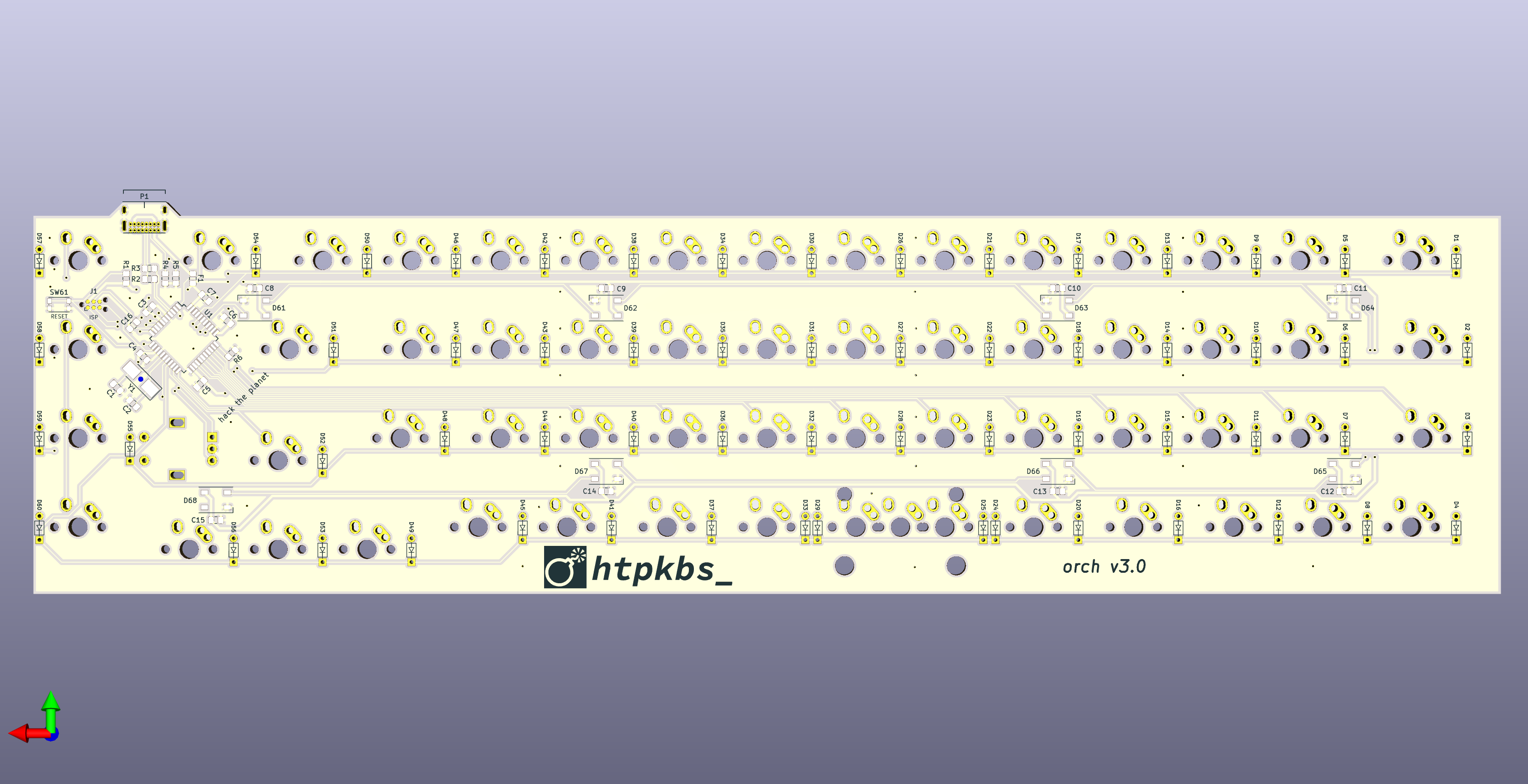
Orch is an open-source printed circuit board by htpkbs, from the htpkbs/orch repository on GitHub, published under the BSD-2-Clause licence. It is a 2-layer board of 313.6 × 83.8 mm with 157 parts on 110 nets, routed with 777 tracks and 74 vias.
It is built around the ATMEGA32U4-AU and SK6812. Its parts include 68 diodes, 61 switches, 16 capacitors, 6 resistors and 2 connectors. It belongs with the keyboards and input boards and the AVR (ATmega, ATtiny) boards of this library.


The orch is a keyboard PCB.
It has:
The key layout looks like this. (Thanks to Keyboard Layout Editor for the image.)
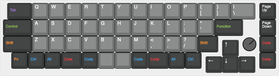
This is the corresponding data for pasting into Keyboard Layout Editor:
[{x:0.25,c:"#393b3b",t:"#9065c7",a:6,w:1.5},"Tab",{c:"#727474",t:"#c6c9c7",a:4,f:5},"Q","W","E","R","T","Y","U","I","O","P","{\n[","}\n]",{w:1.5},"|\n\\",{c:"#393b3b",x:0.25,t:"#c6c9c7",a:4,f:3},"Page\n\n\n\n\n\nUp"],
[{t:"#689b34",a:6,w:1.75},"Control",{c:"#727474",t:"#c6c9c7",a:4,f:5},"A","S","D","F","G","H","J","K","L",":\n;","\"\n'",{c:"#393b3b",t:"#689b34",a:6,f:3,w:1.75},"Function",{x:1,t:"#c6c9c7",a:4},"Page\n\n\n\n\n\nDown"],
[{t:"#ee6d00",a:6,w:1.75},"Shift",{c:"#727474",t:"#c6c9c7",a:4,f:5},"Z","X","C","V","B","N","M","<\n,",">\n.","?\n/",{c:"#393b3b",t:"#ee6d00",a:6,f:3,w:1.25},"Shift",{x:2.5,t:"#dd1126"},"Code"],
[{y:-0.75,x:13.25,t:"#c6c9c7",a:4,f:5},"↑"],
[{y:-0.25,x:0.5,t:"#ee6d00",a:6,f:3},"Fn",{t:"#0084c2"},"Ctrl","Alt",{t:"#dd1126",w:1.25},"Code",{t:"#0084c2"},"Code",{c:"#727474",t:"#000000",a:7},"","",{c:"#393b3b",t:"#0084c2",a:6},"Code",{t:"#dd1126",w:1.25},"Code",{t:"#0084c2"},"Alt","Ctrl",{x:3.5,t:"#dd1126"},"Code"],
[{y:-0.75,x:12.25,t:"#c6c9c7",a:4,f:5},"←","↓","→"]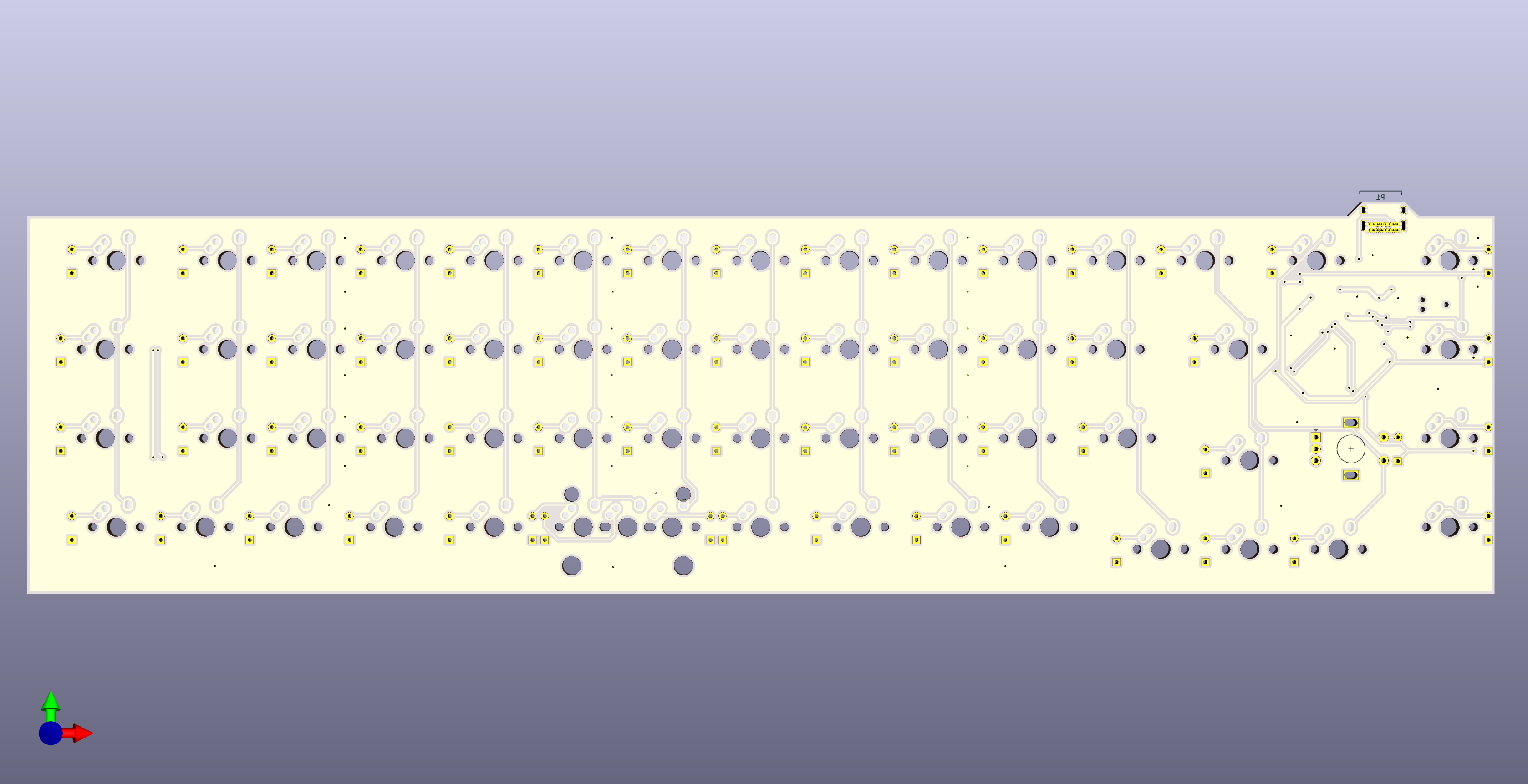
Case files are in the case directory and include a cutout for the rotary encoder. The "closed" layer requires some dremeling or filing to make room for the USB connector. Thanks to the swillkb Plate & Case Builder. There are two bottom case files included. One of them has smaller holes that are meant for tapping (to secure the screws directly into the back case layer), and the other has "open" holes that an M2 screw will fit through (to secure the case together with nuts).
There is a PDF of the schematic here.
These are just some notes on programming the ATmega32U4. The datasheet is here.
ISP headers are included in the "No Legs" Tag-Connect format. You need a Tag-Connect cable and retaining clip board to connect to it. For example, if you have an AVRISP mkII programmer, you need the "No Legs" cable and the retaining clip board.
Default values are:
E:F3, H:99, L:5E| Name | Bit | Value | Status | Reason |
|---|---|---|---|---|
| - | 7 | 1 | Unprogrammed | Unused |
| - | 6 | 1 | Unprogrammed | Unused |
| - | 5 | 1 | Unprogrammed | Unused |
| - | 4 | 1 | Unprogrammed | Unused |
| HWBE | 3 | 0 | Programmed | Pin used to force bootloader after reset |
| BODLEVEL2 | 2 | 0 | Programmed | 4.3V brown-out reset threshold |
| BODLEVEL1 | 1 | 0 | Programmed | 4.3V brown-out reset threshold |
| BODLEVEL0 | 0 | 0 | Programmed | 4.3V brown-out reset threshold |
Hex value is F0.
| Name | Bit | Value | Status | Reason |
|---|---|---|---|---|
| OCDEN | 7 | 1 | Unprogrammed | OCD disabled |
| JTAGEN | 6 | 0 | Programmed | JTAG enabled |
| SPIEN | 5 | 0 | Programmed | SPI enabled |
| WDTON | 4 | 1 | Unprogrammed | Watchdog timer in interrupt mode |
| EESAVE | 3 | 1 | Unprogrammed | EEPROM preserved on chip erase |
| BOOTSZ1 | 2 | 0 | Programmed | Default maximum boot size |
| BOOTSZ0 | 1 | 0 | Programmed | Default maximum boot size |
| BOOTRST | 0 | 1 | Unprogrammed | 4.3V brown-out reset threshold |
Hex value is 99.
| Name | Bit | Value | Status | Reason |
|---|---|---|---|---|
| CKDIV8 | 7 | 1 | Unprogrammed | Don't divide clock by 8 |
| CKOUT | 6 | 1 | Unprogrammed | Don't output clock |
| SUT1 | 5 | 0 | Programmed | Crystal oscillator with BOD enabled |
| SUT0 | 4 | 1 | Unprogrammed | Crystal oscillator with BOD enabled |
| CKSEL3 | 3 | 1 | Unprogrammed | Low power 16MHz crystal oscillator |
| CKSEL2 | 2 | 1 | Unprogrammed | Low power 16MHz crystal oscillator |
| CKSEL1 | 1 | 1 | Unprogrammed | Low power 16MHz crystal oscillator |
| CKSEL0 | 0 | 1 | Unprogrammed | Crystal oscillator with BOD enabled |
Hex value is DD.
avrdude commands to set the fuse values with an AVRISP mkII programmer:
avrdude -p m32u4 -c avrispmkII -U efuse:w:0xF0:m
avrdude -p m32u4 -c avrispmkII -U hfuse:w:0x99:m
avrdude -p m32u4 -c avrispmkII -U lfuse:w:0xDD:m
Note that the extended fuse will always show as C0 with avrdude (despite the datasheet saying that the first four bits are unprogrammed/1111).
You may need to erase the chip before you set the fuse values:
avrdude -p m32u4 -c avrispmkII -eThe first time flashing should be done with a programmer like the AVRISP mkII and you should compile QMK to include the bootloader in the firmware file (using :production). I have a fork of the qmk_firmware repository here that I may or may not try to get merged at some point.) To compile the orch branch with the QMK CLI:
qmk compile -kb orch -km default:productionI've had luck setting a custom bitclock setting (-B) for the initial flash when using the mkII, but this may not matter. For example:
avrdude -p m32u4 -c avrispmkII -U flash:w:orch_default_production.hex:i -B 154.37You should now be able to flash regular (non-:production) firmware that doesn't include the bootloader over USB using QMK Tookbox.
D_DO-35_SOD27_P5.08mm_Horizontal.kicad_mod and USB_C_GCT_USB4085.kicad_mod. The Creative Commons license for these is included here.MX* symbols. The MIT license for these is included here.| Qty | Value | Footprint | References |
|---|---|---|---|
| 60 | 1N4148 | orch:D_DO-35_SOD27_P5.08mm_Horizontal | D1, D2, D10, D11, D12, D13, D14, D15, D16, D17, D18, D19, D20, D21, D22, D23 +44 |
| 50 | MX-NoLED | orch:MX-1U-NoLED | SW10, SW11, SW12, SW13, SW14, SW15, SW17, SW18, SW19, SW20, SW21, SW22, SW23, SW24, SW26, SW27 +34 |
| 12 | 0.1u | Capacitor_SMD:C_0805_2012Metric_Pad1.18x1.45mm_HandSolder | C4, C5, C6, C7, C8, C9, C10, C11, C12, C13, C14, C15 |
| 8 | SK6812 | LED_SMD:LED_SK6812_PLCC4_5.0x5.0mm_P3.2mm | D61, D62, D63, D64, D65, D66, D67, D68 |
| 3 | MX-NoLED | orch:MX-1.25U-NoLED | SW16, SW37, SW48 |
| 3 | MX-NoLED | orch:MX-1.75U-NoLED | SW2, SW3, SW51 |
| 2 | 22R | Resistor_SMD:R_0805_2012Metric_Pad1.15x1.40mm_HandSolder | R2, R3 |
| 2 | 22pF | Capacitor_SMD:C_0805_2012Metric_Pad1.18x1.45mm_HandSolder | C1, C2 |
| 2 | 5.1k | Resistor_SMD:R_0805_2012Metric_Pad1.15x1.40mm_HandSolder | R4, R5 |
| 2 | MX-NoLED | orch:MX-1.5U-NoLED | SW1, SW54 |
| 1 | 100mA | Fuse:Fuse_0805_2012Metric_Pad1.15x1.40mm_HandSolder | F1 |
| 1 | 10K | Resistor_SMD:R_0805_2012Metric_Pad1.15x1.40mm_HandSolder | R6 |
| 1 | 10k | Resistor_SMD:R_0805_2012Metric_Pad1.15x1.40mm_HandSolder | R1 |
| 1 | 16MHz | Crystal:Crystal_SMD_Abracon_ABM3-2Pin_5.0x3.2mm_HandSoldering | Y1 |
| 1 | 1u | Capacitor_SMD:C_0805_2012Metric_Pad1.18x1.45mm_HandSolder | C16 |
| 1 | 4.7u | Capacitor_SMD:C_0805_2012Metric_Pad1.18x1.45mm_HandSolder | C3 |
| 1 | ATmega32U4-AU | Package_QFP:TQFP-44_10x10mm_P0.8mm | U1 |
| 1 | AVR-ISP-6 | Connector:Tag-Connect_TC2030-IDC-NL_2x03_P1.27mm_Vertical | J1 |
| 1 | LOGO | orch:htpkbs | G*** |
| 1 | MX-NoLED | orch:MX-2U-NoLED | SW25 |
| 1 | Reset | Button_Switch_SMD:SW_Push_1P1T_NO_CK_KMR2 | SW61 |
| 1 | Rotary_Encoder_Switch | orch:RotaryEncoder_Alps_EC11E-Switch_Vertical_H20mm | SW55 |
| 1 | USB_C_Receptacle_USB2.0 | orch:USB_C_GCT_USB4085 | P1 |
It measures 313.6 × 83.8 mm and has 2 copper layers, 1.6 mm thick.
157 parts, built around the ATMEGA32U4-AU and SK6812. The full list of its parts is on this page, with links to each part's symbol and footprint where PCBKit's library has them.
From the htpkbs/orch repository on GitHub, at the commit this page was made from: the board is pcb/orch.kicad_pcb. PCBKit opens the board in the browser, with nothing to install.
Its repository publishes it under the BSD-2-Clause licence: you may reuse it on that licence's terms (keep the author's notice, and for a copyleft licence share your changes alike).
w4ilun/neofighter
A MIDI controller using arcade buttons with RGB lighting effects


kebbn/athene-pcb-32u4
65% PCB design for the Athene keyboard by KL using the ATmega32u4 MCU (No longer supported)

hackclub/OnBoard
💡 Join 1,000 teenagers and make your first PCB with a $100 grant!

conol-ai/openmicrokbd
Open-source recreation of OpenAI's Codex Micro macropad — PCB written in CoHDL, an AI-native hardware description language. Rust firmware (embassy) + companion app (makepad). MIT licensed. https://openmicrokbd.org


cormoran/dya-dash-keyboard
DYA Dash portable wireless split keyboard with 25mm trackball