2 layers43.2 × 17.6 mm

 conol-ai/openmicrokbd154
Open-source recreation of OpenAI's Codex Micro macropad — PCB written in CoHDL, an AI-native hardware description language. Rust firmware (embassy) + companion app (makepad). MIT licensed. https://openmicrokbd.org
Openmicro is an open-source printed circuit board by conol-ai, from the conol-ai/openmicrokbd repository on GitHub, published under the MIT licence. It is a 4-layer board of 95 × 95 mm with 88 parts on 65 nets, routed with 1,500 tracks and 216 vias.
It is built around the STM32F072CBT6, USBLC6-4 and SK6812. Its parts include 34 diodes, 25 capacitors, 14 switches, 3 resistors and 3 ICs. It belongs with the keyboards and input boards and the STM32 boards of this library.


An open-source hardware recreation of OpenAI's Codex Micro macropad — 13 low-profile keys, a rotary encoder, an analog joystick, a capacitive touch pad, and per-key + underglow RGB on a wired USB-C board built around an STM32F072.
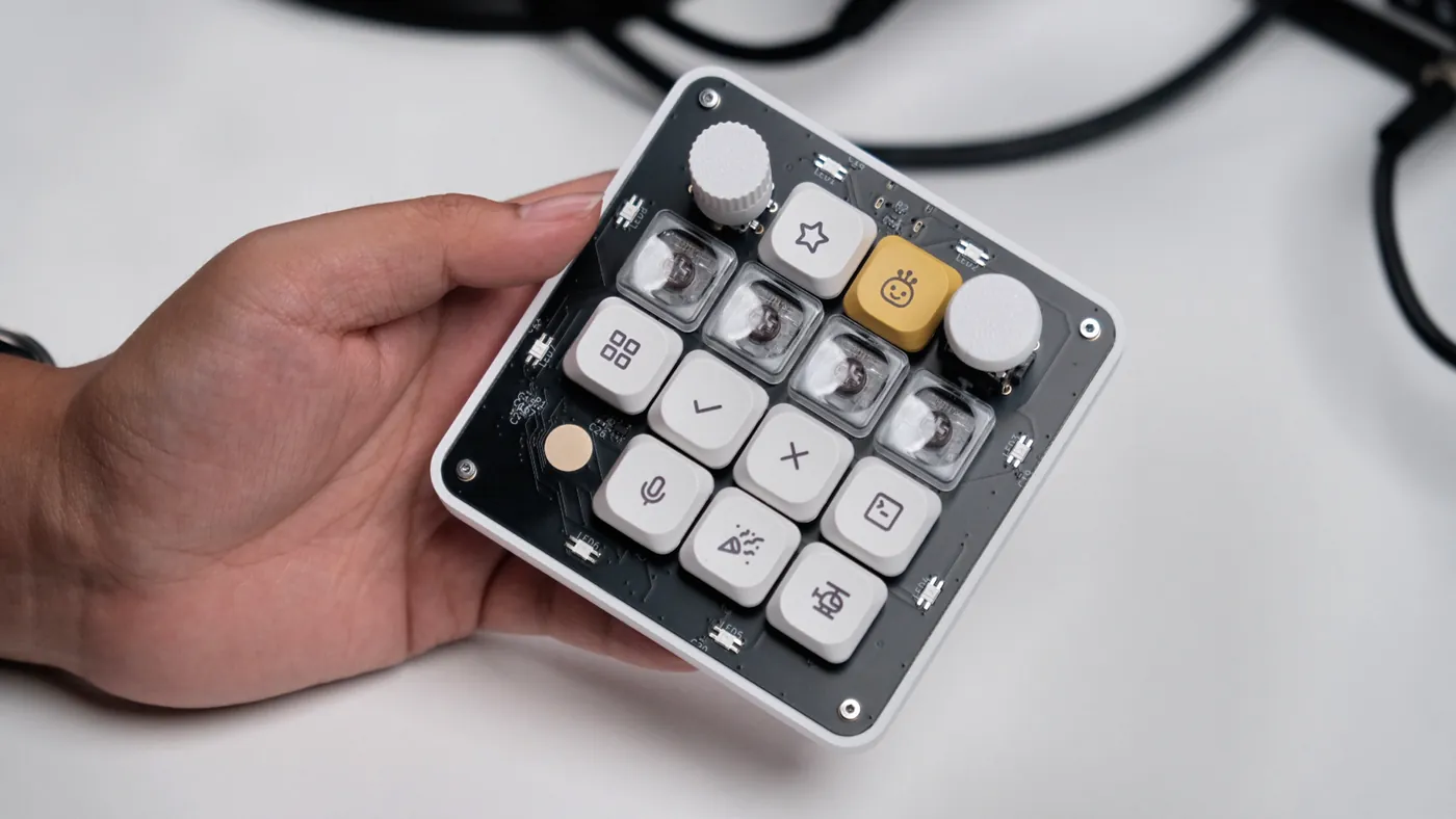
The finished board — read the launch post for the full story.
The PCB is written, not drawn. The entire schematic is source code in CoHDL, an open-source, AI-native hardware description language. The compiler type-checks the design — units, pin-connection obligations, power integrity — and emits the netlist, BOM, footprints and layout constraints you can inspect under hw/v1/out/.
🌐 https://openmicrokbd.org · 🖨️ Printable case on MakerWorld (中国站) · License: MIT
This board was designed in CoHDL, an open-source hardware description language that makes schematic (PCB) design AI-native: a board is a program — typed, checked, and compiled. In CoHDL, the design in hw/v1/src/ is the schematic; the compiler is the oracle that grades it.
CoHDL is open source. Visit cohdl.org to explore the language, or browse and contribute to the compiler and libraries on GitHub. This repository also checks in the complete compiler outputs under hw/*/out/, so the generated hardware design remains directly inspectable.
Questions about CoHDL, the hardware source, or building a board of your own? Join the CoHDL and OpenMicroKbd community on Discord.
| Path | Contents |
|---|---|
hw/v1/src/ | The PCB as CoHDL source: main.cohdl (top-level design), openmicro_parts.cohdl (datasheet-verified part bindings), footprints.cohdl, pads.cohdl |
hw/v1/out/ | Checked-in compiler output: KiCad netlist (openmicro.net), BOM (openmicro-bom.csv), SMT placement (openmicro-smt.csv), .kicad_mod footprints, layout constraints (openmicro-layout.json) |
hw/v1/pcb/ | The routed board — openmicro.kicad_pcb + KiCad project (design rules) |
hw/v1/fab/ | Manufacturing package: Gerber/drill zip, assembly BOM, SMT placement CSV — see hw/v1/fab/README.md |
hw/v1/mechanical/ | Board outline (DXF) plus the printable enclosure parts — case, rotary knob, joystick cap, shipping tray and a solder-assembly jig, as editable Fusion 360 .f3d and ready-to-slice .3mf. Also published as a print profile on MakerWorld (中国站) |
hw/v1/docs/ | Manufacturer datasheets for every active, connector, and electromechanical part in the BOM, with sourcing/verification notes — see hw/v1/docs/README.md |
hw/v2/ | Hardware v2, in development — wireless successor on the SiFli SF32LB52 (BLE, battery-powered): CoHDL source + compiler outputs, not yet routed. See hw/v2/README.md |
layout/ | The bootloader/firmware/host contract: flash and RAM map, image header, handoff words, HID update protocol, CRC-32 — no_std, shared by fw, boot, app and scripts/ |
boot/ | Resident 24 KiB bootloader at 0x08000000: validates the application by length and CRC-32 before every start and offers a driverless USB HID update mode, so an interrupted update never bricks the pad. See boot/README.md |
fw/ | Firmware — Rust + embassy on STM32F072CB: key matrix, twin WS2812 chains, USB HID + vendor interface, driverless updates through the resident bootloader (ROM DFU kept for migration and recovery), and an opt-in Codex Micro compat mode (the pad boots with the Codex Micro's USB identity and speaks ChatGPT Desktop's device protocol so the desktop app drives it natively — confirmed with Codex desktop 26.825 on macOS). See fw/README.md |
app/ | Companion desktop app — Rust + GPUI, with a crisp 8-bit visual system: device dashboard, live connection state, and button-free firmware updates over USB. See app/README.md |
# Production firmware binary + debug ELF
scripts/build-firmware.sh dist

# Native GPUI macOS app bundle + DMG (ad-hoc signed for local testing)
scripts/package-macos.sh dist dist/openmicro-fw-<firmware-version>.bin

# Or run the companion app from source
cd app && cargo run --release --locked
On Windows, install Rust and Visual Studio's Desktop development with C++ workload, then build a portable package from PowerShell:
rustup target add x86_64-pc-windows-msvc
./scripts/package-windows.ps1 `
  -OutputDir dist/windows `
  -FirmwareBin dist/openmicro-fw-<firmware-version>.bin `
  -Target x86_64-pc-windows-msvc
Use aarch64-pc-windows-msvc for a native Windows on Arm package; that build
also requires the Visual Studio LLVM/Clang component.
The open-source CoHDL compiler and its documentation are available at cohdl.org. Generated netlists, BOMs, footprints, and layout constraints remain checked in under hw/*/out/ for inspection and use without rerunning the toolchain.
Releases build Intel and Apple Silicon DMGs, Windows x64 and Arm64 portable
ZIPs, and firmware through GitHub Actions. See
RELEASING.md for versioning, Apple signing/notarization
secrets, the required device smoke test, and the tag flow.
Linux packaging, USB permissions, and the STM32F072 ROM-DFU host-controller
workaround are tracked in
docs/linux-firmware-updates.md.
The final routed v1 board lives in hw/v1/pcb/ (openmicro.kicad_pcb, opens in KiCad 9+). The manufacturing package — Gerber/drill zip, assembly BOM, and SMT pick-and-place CSV, ready to upload to a fab such as JLCPCB — is in hw/v1/fab/, with DRC status and ordering notes in hw/v1/fab/README.md.
The enclosure is published as a ready-to-print model on MakerWorld, alongside the editable Fusion sources in hw/v1/mechanical/:
The print covers the case, the rotary knob and the joystick cap, plus the solder-assembly jig and the shipping package as a bonus from the same project. Recommended settings: 0.4 mm nozzle, 0.2 mm layer height, 3 walls, 15–20% infill, PLA or PETG (PETG for a daily driver), no supports required.
Beyond the print you will need an assembled PCB, Choc V2-compatible keycaps, M2×4 female-female brass standoffs, M2×5 screws, and a USB-C cable.
MIT © 2026 Tony Huang. Build your own — attribution appreciated.
OpenMicroKbd is an independent open-source project and is not affiliated with, endorsed by, or sponsored by OpenAI. "Codex Micro" refers to OpenAI's product; all trademarks belong to their respective owners.
| Qty | Value | Footprint | References |
|---|---|---|---|
| 21 | 100nF | passive-CHIP_0402 | C1, C2, C3, C4, C10, C11, C12, C13, C14, C15, C16, C17, C18, C19, C20, C21 +5 |
| 21 | SK6812 | led-FP_LED_SK6812MINI_E | LED1, LED2, LED3, LED17, LED18, LED19, LED20, LED21, LED22, LED23, LED24, LED25, LED26, LED27, LED28, LED29 +5 |
| 13 | Diode_1N4148 | diode-FP_D_SOD_123 | D1, D2, D3, D4, D5, D6, D7, D8, D9, D10, D11, D12, D13 |
| 13 | KeySwitch | openmicro-FP_SW_Choc_V2 | SW3, SW4, SW5, SW6, SW7, SW8, SW9, SW10, SW11, SW12, SW13, SW14, SW15 |
| 4 | MountingHole | openmicro-FP_MountingHole_M2 | H1, H2, H3, H4 |
| 2 | 15pF | passive-CHIP_0402 | C28, C29 |
| 2 | 5.1kohm | passive-CHIP_0402 | R2, R3 |
| 1 | 10kohm | passive-CHIP_0402 | R1 |
| 1 | 1uF | passive-CHIP_0402 | C27 |
| 1 | 4.7uF | passive-CHIP_0603 | C26 |
| 1 | AP2112K_3V3 | ldo-SOT5P95X290X160N | U2 |
| 1 | CapTouchPad | openmicro-FP_TouchPad | TP1 |
| 1 | Crystal8MHz | osc-FP_Crystal_3225 | Y1 |
| 1 | RotaryEC11 | openmicro-FP_Encoder_EC11 | SW1 |
| 1 | STM32F072CBT6 | st_stm32-f0-stm32f072cb-QFP50P900X900X160_48N | U3 |
| 1 | Socket_2x3 | connectors-headers-smd_254-FP_Socket_2x3_254_SMD | J2 |
| 1 | ThumbPointer | openmicro-FP_Joystick_RKJXV | J1 |
| 1 | USBLC6 | esd-FP_SOT_23_6 | U1 |
| 1 | USB_C_Receptacle_2_0 | usb-connectors-type_c-FP_USB_C_Receptacle_HRO_TYPE_C_31_M_12 | J3 |
It measures 95 × 95 mm and has 4 copper layers, 1.6 mm thick.
88 parts, built around the STM32F072CBT6, USBLC6-4 and SK6812. The full list of its parts is on this page, with links to each part's symbol and footprint where PCBKit's library has them.
From the conol-ai/openmicrokbd repository on GitHub, at the commit this page was made from: the board is hw/v1/pcb/openmicro.kicad_pcb. PCBKit opens the board in the browser, with nothing to install.
Its repository publishes it under the MIT licence: you may reuse it on that licence's terms (keep the author's notice, and for a copyleft licence share your changes alike).

Jana-Marie/EF-S-Adapter
Hard- and Firmware to control different EF and EF-S lenses

OpenElectronicsLab/OpenHardwareExG
The OpenHardwareExG is a platform for ECG, EEG, EMG, ENG, EOG, and evoked potential applications. http://openelectronicslab.github.io/OpenHardwareExG/


electricui/electricui-arena
Hardware for continuous integration testing of serial interfaces and microcontrollers

