2 layers129.9 × 63.6 mm
Traeger rev 2.3.0.kicad pro
jazzmonger/Traeger-PID-Controller
Traeger Smoker/Grill Controller based on an
45 parts36

 hpvdt/oven2
Generic Composite Oven Controller
Oven rev1 is an open-source printed circuit board by hpvdt, from the hpvdt/oven repository on GitHub. It is a 2-layer board of 54.6 × 108 mm with 21 parts on 39 nets, routed with 164 tracks and 18 vias.
It is built around the ATMEGA328-AU and MAX6675ISA+. Its parts include 10 connectors, 4 capacitors, 2 ICs, 1 resistor and 1 crystal. It belongs with the AVR (ATmega, ATtiny) boards of this library.


Our team's generic composite oven controller. Used to maintain a desired two-step curing cycle recommended for the majority of our composites. Each step is defined with a target temperature, a ramp speed to reach it at (e.g. 2 degC/minute), and hold time at that temperature.
The control system is pretty simple, a single K-type thermocouple is used to monitor the temperature in the oven, and a simple "ON/OFF" scheme is used to operate the relay that controls the power to the heater. Turning ON when below a threshold, and then OFF once the upper threshold is surpassed.
User input is handled by a 16 button keypad, with a 20 by 4 character LCD screen used for feedback to the user to inform them of their input, and the current state of the oven.
With the exception of the display code (under "libraries") all the code was written by hand
in the Arduino IDE. The main firmware is oven_system which is written for an Arduino Nano.
It was previously modified to include logging capabilities (oven_system_with_logging),
and another version to operate using the serial interface for input/output in the absence
of a keybad and/or a screen (oven_system_no_display). These variants have not been
maintained to include recent improvements to the main code!
In addition to the main code, we also prepared unit tests for each piece of hardware we were introducing to the system. In these we wrote the code needed to interact with each part as well as running some basic tests to exercise both the code and component. These are all in the "unit_tests" folder.
The current design is a small circuit board which has the ATmega328P microcontroller and the MAX6675 thermocouple chip. The microcontroller is set up to be programmed just like an Arduino Nano. Off board is the solid state relay used to regulate the heater, the 5V supply, keypad, and screen. This is all housed in a metal case repurposed from a failed power supply, with the terminal block used to connect the thermocouple, power, and heater.
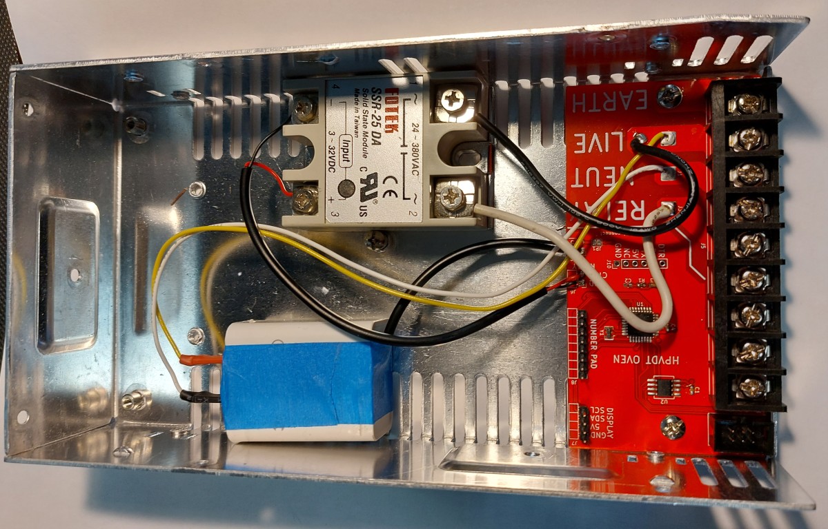
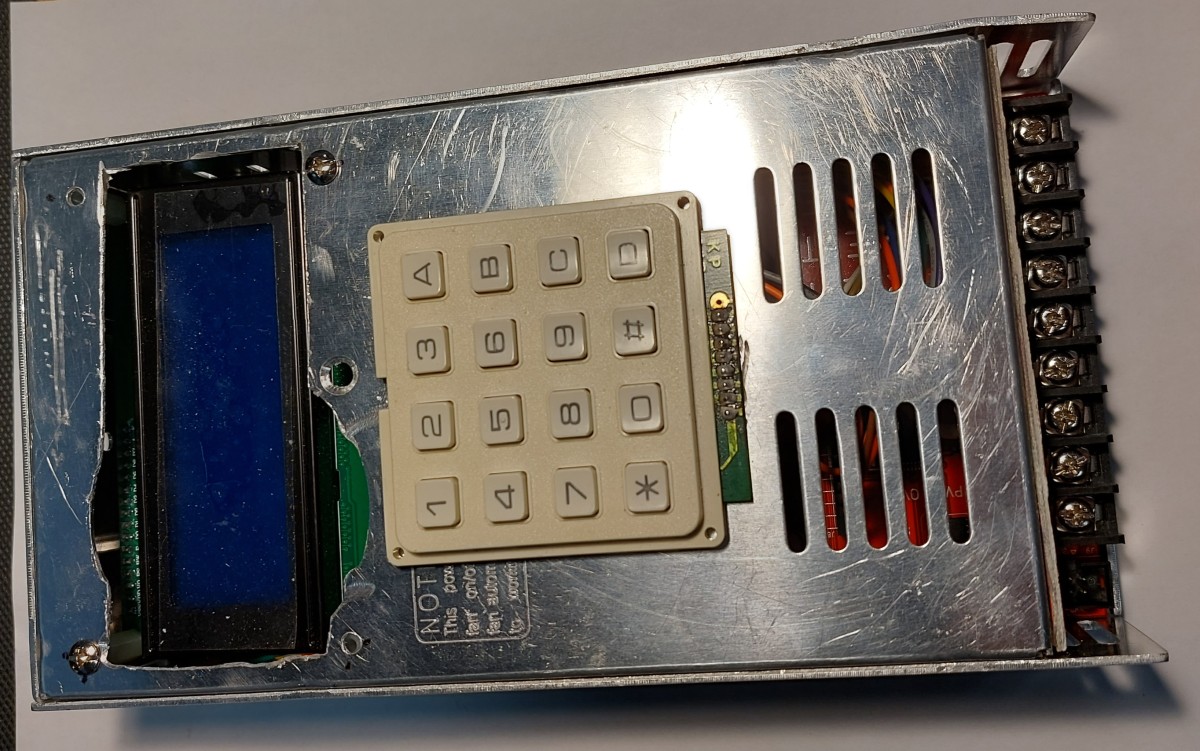
The current board was designed in KiCad 6, however my previous versions were designed in EAGLE. The most notable differences through iterations are:
A small to-do list of future features that could improve the system.
| Qty | Value | Footprint | References |
|---|---|---|---|
| 3 | 100n | Capacitor_SMD:C_0603_1608Metric | C1, C3, C4 |
| 1 | 10K | Resistor_SMD:R_0603_1608Metric | R1 |
| 1 | 16M | Crystal:Resonator_SMD_muRata_CSTxExxV-3Pin_3.0x1.1mm | Y1 |
| 1 | 4n7 | Capacitor_SMD:C_0603_1608Metric | C2 |
| 1 | 5V_IN | Connector_PinHeader_2.54mm:PinHeader_1x02_P2.54mm_Horizontal | J2 |
| 1 | 5V_{SUP} | Jumper:SolderJumper-2_P1.3mm_Bridged_Pad1.0x1.5mm | JP1 |
| 1 | ATmega328-AU | Package_QFP:TQFP-32_7x7mm_P0.8mm | U1 |
| 1 | AVR-ISP-6 | Connector_IDC:IDC-Header_2x03_P2.54mm_Vertical | J9 |
| 1 | DISPLAY | Connector_PinHeader_2.54mm:PinHeader_1x04_P2.54mm_Horizontal | J7 |
| 1 | LIVE | Connector_Wire:SolderWire-2sqmm_1x02_P7.8mm_D2mm_OD3.9mm | J4 |
| 1 | M3 | MountingHole:MountingHole_3.5mm_Pad_Via | H1 |
| 1 | M3 | MountingHole:MountingHole_3.5mm | H2 |
| 1 | MAX6675 | Package_SO:SO-8_5.3x6.2mm_P1.27mm | U2 |
| 1 | NEUTRAL | Connector_Wire:SolderWire-2sqmm_1x01_D2mm_OD3.9mm | J1 |
| 1 | NUMPAD | Connector_PinHeader_2.54mm:PinHeader_1x08_P2.54mm_Horizontal | J8 |
| 1 | OUTPUT | oven:9POS-TERMBLOCK | J5 |
| 1 | RELAY_CTRL | Connector_PinHeader_2.54mm:PinHeader_1x02_P2.54mm_Horizontal | J6 |
| 1 | RELAY_PWR | Connector_Wire:SolderWire-2sqmm_1x01_D2mm_OD3.9mm | J3 |
| 1 | SERIAL | Connector_PinHeader_2.54mm:PinHeader_1x06_P2.54mm_Vertical | J10 |
It measures 54.6 × 108 mm and has 2 copper layers, 1.6 mm thick.
21 parts, built around the ATMEGA328-AU and MAX6675ISA+. The full list of its parts is on this page, with links to each part's symbol and footprint where PCBKit's library has them.
From the hpvdt/oven repository on GitHub, at the commit this page was made from: the board is hardware/oven_rev1/oven_rev1.kicad_pcb and its schematic hardware/oven_rev1/oven_rev1.kicad_sch. PCBKit opens the board in the browser, with nothing to install.
Its repository states no licence, so its author keeps all rights: ask hpvdt before reusing the design.
jazzmonger/Traeger-PID-Controller
Traeger Smoker/Grill Controller based on an


FHafting/BREAD
This project is fully documented in the paper: Shane Oberloier, Nicholas G. Whisman, Finn Hafting, Joshua M. Pearce, Open Source Framework for a Broadly Expandable and Reconfigurable Data Acquisition and Automation…


LKbrilliant/Brilliant-Reflow
A complete DIY solution for converting a consumer oven into a temperature controlled reflow oven for PCB soldering