2 layers244 × 244 mm

 hkzlab/TurboXT_Addon15
8Mhz Turbo / Reset addon board for the IBM 5160 (The original XT)
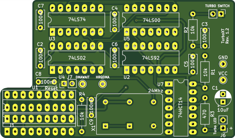
TurboXT is an open-source printed circuit board by hkzlab, from the hkzlab/TurboXT_Addon repository on GitHub. It is a 2-layer board of 74.3 × 43.8 mm with 28 parts on 36 nets, routed with 333 tracks and 2 vias.
It is built around the 74HCT14D, 74LS00SC and 74LS02PC, with the 74LS74PC among its other parts. Its parts include 9 capacitors, 7 connectors, 6 ICs, 4 resistors and 1 switch. It belongs with the retro computing and games boards of this library.


This board is originally based on schematics I found floating around on VCFED, and adds the following to an IBM XT:
I take NO responsibility for what happens if you decide to build and use this card. Your computer might crash, catch fire or be destroyed in other nasty ways. Also, as this card is mostly based on the work of others, You're encourauged to take what you deem fit from this, and use it in your projects!
The board is installed on the 8284 socket (near the 8088 processor) via turned pin headers, and the 8284 is placed on a socket on top of the board. Usually, an additional socket is added to the bottom headers to gain some vertical spacing, as part of the board sits above 8088 and 8087 sockets.
The TurboXT then has 4 additional labeled connections to make on the motherboard via wire.
These connections are required to automatically disable turbo during DMA:
Note that these two connections actually end up feeding into the same NAND gate, you can mix them up and no issue will arise.
These are optional but highly recommended to provide an additional source of power beside the 8284 socket:
There are many connection points you can use (VCC/GND legs of another IC for example), but along the side of the XT power connector there are two empty resistor footprints on my board that were perfect for the connection.
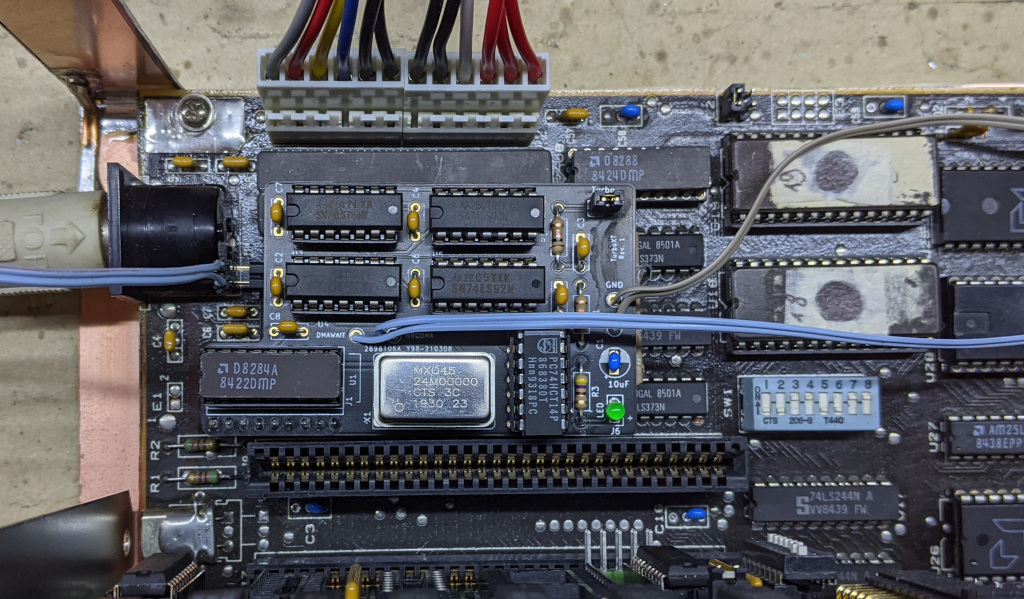
Check continuity with a multimeter!!!
Original schematics from this thread on VCFED.
| Qty | Value | Footprint | References |
|---|---|---|---|
| 8 | 100nF | Capacitor_THT:C_Disc_D6.0mm_W2.5mm_P5.00mm | C2, C3, C4, C5, C6, C7, C8, C9 |
| 3 | 10k | Resistor_THT:R_Axial_DIN0207_L6.3mm_D2.5mm_P10.16mm_Horizontal | R1, R2, R4 |
| 1 | 10uF | Capacitor_THT:CP_Radial_D5.0mm_P2.50mm | C1 |
| 1 | 24Mhz | ISA_DualUART:Oscillator_DIP-14-8 | X1 |
| 1 | 470 | Resistor_THT:R_Axial_DIN0207_L6.3mm_D2.5mm_P10.16mm_Horizontal | R3 |
| 1 | 74HCT14 | Package_DIP:DIP-14_W7.62mm_LongPads | U7 |
| 1 | 74LS00 | Package_DIP:DIP-14_W7.62mm_LongPads | U5 |
| 1 | 74LS02 | Package_DIP:DIP-14_W7.62mm_LongPads | U4 |
| 1 | 74LS74 | Package_DIP:DIP-14_W7.62mm_LongPads | U3 |
| 1 | 74LS92 | Package_DIP:DIP-14_W7.62mm_LongPads | U2 |
| 1 | 8284 | Package_DIP:DIP-18_W7.62mm_Socket_LongPads | U1 |
| 1 | 8284 Socket | Package_DIP:DIP-18_W7.62mm_LongPads | J1 |
| 1 | DMAWAIT | Connector_Pin:Pin_D1.0mm_L10.0mm | J3 |
| 1 | GND | Connector_Pin:Pin_D1.0mm_L10.0mm | J5 |
| 1 | HRQDMA | Connector_Pin:Pin_D1.0mm_L10.0mm | J2 |
| 1 | Reset | Connector_PinHeader_2.54mm:PinHeader_1x02_P2.54mm_Vertical | J7 |
| 1 | TURBO SWITCH | Connector_PinHeader_2.54mm:PinHeader_1x02_P2.54mm_Vertical | SW1 |
| 1 | Turbo LED | Connector_PinHeader_2.54mm:PinHeader_1x02_P2.54mm_Vertical | J6 |
| 1 | VCC | Connector_Pin:Pin_D1.0mm_L10.0mm | J4 |


RetroStack/TRS-80-Model-I-G-E1
Hardware Replica of the TRS-80 Model I Revision G

hkzlab/CGA_Redux
The Color Graphics Adapter Redux board is a more or less faithful clone of the original IBM CGA, based on the original schematics


It measures 74.3 × 43.8 mm and has 2 copper layers, 1.6 mm thick.
28 parts, built around the 74HCT14D, 74LS00SC, 74LS02PC and 74LS74PC. The full list of its parts is on this page, with links to each part's symbol and footprint where PCBKit's library has them.
From the hkzlab/TurboXT_Addon repository on GitHub, at the commit this page was made from: the board is TurboXT.kicad_pcb. PCBKit opens the board in the browser, with nothing to install.
Its repository states no licence, so its author keeps all rights: ask hkzlab before reusing the design.