2 layers39.4 × 57.2 mm
Pod 27C040
hkzlab/ROsiM
ROsiM is a ROM simulator/emulator, supporting up to 512k/16bit ROMs
13 parts11GPL-3.0

 hkzlab/ROsiM11
ROsiM is a ROM simulator/emulator, supporting up to 512k/16bit ROMs
ROsiM is an open-source printed circuit board by hkzlab, from the hkzlab/ROsiM repository on GitHub, published under the GPL-3.0 licence. It is a 2-layer board of 170.2 × 78.7 mm with 93 parts on 144 nets, routed with 3,252 tracks and 176 vias.
It is built around the ATMEGA328-PU, 74HCT244D and 74HC244D, with the FT232RL, 74HC595 and 74HC166D among its other parts. Its parts include 31 resistors, 24 capacitors, 18 ICs, 6 connectors and 5 diodes. It belongs with the retro computing and games boards and the AVR (ATmega, ATtiny) boards of this library.


The ROsiM is a ROM simulation / emulation board: it uses two 512k/8bit SRAM chips to simulate an 8 or 16 bit ROM (up to 512k bytes or 512k words in size).
The board is based around an ATMega328P chip @20Mhz, controlled via serial connection.
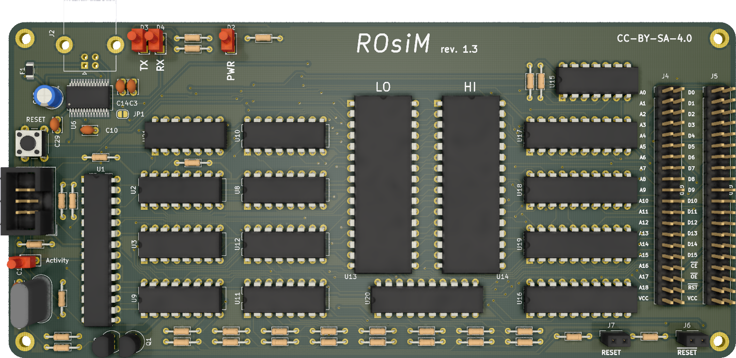
I made this out of my personal need of a simple way to quickly test ROM images on boards I repair/hack/build. Often, these boards use big 16bit EPROMs and the projects I found around did not cater to my needs.
The idea is to use this bare board and then "pods" that attach to the two 40pin header and adapt it to simulate various types of ROMs.
WARNING: While I might help you with quick questions, there is NOT going to be hand-holding for this one.
I have currently built and tested revision 1.3 of this board. The following fixes must be implemented to make it usable:
The following mod is optional but encouraged for safety, and have been implemented for revision 1.4:
This board is designed around relatively cheap through hole (with a few exceptions) components, and should be buildable by anyone with basic soldering skills.
You'll need a way to program your 328P MCU with the bootloader (you can then load the firmware via serial port).
I recommend optiboot. Remember to set the AVR frequency to 20Mhz and baudrate to 115200bps. I might provide prebuilt binaries of this in the future.
TODO
This is used for in-circuit programming of the MCU. You won't really use after burning the bootloader to the chip. You can leave this out if you pre-program the ATMega.
Connect your USB cable here. It will appear as an FTDI serial port to the host.
The Interface runs at 230400bps 8-n-1. The protocol is mainly ASCII based, but meant to be used with an external software.
Connect your DC power supply here, center tip positive. Anything between 7 to 9V will be good, 12V will work, but the regulator might get hotter. 500mA should be enough.
A 40 pin header:
A 40 pin header:
An active-low OC signal will be present on this header. You can use to pilot the /RESET of your target board.
Solder an arc of rigid wire on this one, so you can attach a small crocodile clip to it.
An active-high signal (either high or disconnected) will be present on this header.
Solder an arc of rigid wire on this one, so you can attach a small crocodile clip to it.
While this board can be controlled directly via a simple serial terminal, it is advised to use a client software that supports the following protocol, like the ROsiM Loader.
The Remote Control protocol is pretty simple and ASCII based. It supports 12 commands, each with its own syntax and response.
String CMD_ERR will be sent in case the command is not recognized, string CMD_INV will be sent in case the command cannot be executed at this time.
>K<Forces the reset by watchdog of the ROsiM.
>M<[M xx]Returns the current model of the board in hex.
>A 00xxxxxx<[A 00xxxxxx]Specifies the start address for the next read/write commands. The address must be specified in hex, and a mask of 0x7FFFF will be applied to it.
>W xxxx<[W xxxx]The SRAM must be in WRITE mode and the board switched to INTERNAL, otherwise the response CMD_INV will be sent.
xxxx is the data to write on SRAM at the current address in hex format.
Once the write completes, the address will automatically increment by 1.
>R<[R xxxx]The SRAM must be in READ mode and the board switched to INTERNAL, otherwise the response CMD_INV will be sent.
xxxx is the data written at the current address in hex format. Once the read completes, the address will automatically increment by 1.
>E y< where y can be 0 or 1[E y]Enables (1) or disables (0) the external RESET signal to the target board.
>S y< where y can be 0 or 1[S y]To execute this command, the SRAM must be in READ mode, otherwise the response CMD_INV will be sent.
Sets the board to INTERNAL (1) or EXTERNAL (0) mode. EXTERNAL mode will enable the drivers that communicate through the external address/data/control lines.
>X y< where y can be 0 or 1[X y]To execute this command, the board must be in INTERNAL mode, otherwise the response CMD_INV will be sent.
Sets the SRAM to READ (1) or WRITE (0) mode.
>V<[V 00xxxxxx yy]This command will print out the current address in hex format (00xxxxxx) and a mask (yy) in hex format that contains:
>D<[D]Will revert the board state to the following state:
The selection of the EXTERNAL RESET logic will NOT be restored by this command and will remain set to the current state.
>T<[T xx]Resets the board to defaults then executes a test on the SRAMs by writing patterns of data in them and reading them back.
The output can be:
00 test was completed successfully01 test failed while writing the first pattern (0xAA55)02 test failed while writing the first pattern (0x55AA)03 the test failed while writing the incremental pattern>O x<[O yy]Starts an XMODEM transfer of a binary file into the SRAM.
x can be:
0 The file will be considered an 8-bit dump, the highest 8 bits of the SRAM will be set to 0x00, only the lower 8 bits will be set.1 The file will be considered a 16-bit dump, and the data will be loaded into the SRAM in words. ODD bytes in the dump will end up in the high byte of the SRAM, EVEN bytes will end up in the low byte of the SRAM.2 The file will be considered a byte swapped 16-bit dump, and the data will be loaded into the SRAM in words. EVEN bytes in the dump will end up in the high byte of the SRAM, ODD bytes will end up in the low byte of the SRAM.yy will be:
00 for a failed transfer.01 for a successful transfer.| Qty | Value | Footprint | References |
|---|---|---|---|
| 21 | 100nF | Capacitor_THT:C_Disc_D3.4mm_W2.1mm_P2.50mm | C10, C11, C12, C13, C14, C16, C17, C18, C19, C20, C21, C22, C23, C24, C25, C26 +5 |
| 21 | 10K | Resistor_THT:R_Axial_DIN0204_L3.6mm_D1.6mm_P7.62mm_Horizontal | R2, R3, R4, R10, R11, R12, R13, R14, R15, R19, R20, R21, R22, R23, R24, R30 +5 |
| 5 | 74HC595 | Package_DIP:DIP-16_W7.62mm | U2, U3, U9, U11, U12 |
| 4 | MountingHole_Pad | MountingHole:MountingHole_2.7mm_M2.5_ISO7380_Pad | H1, H2, H3, H4 |
| 3 | 4.7K | Resistor_THT:R_Axial_DIN0204_L3.6mm_D1.6mm_P7.62mm_Horizontal | R25, R26, R27 |
| 3 | 74HCT244 | Package_DIP:DIP-20_W7.62mm | U16, U17, U18 |
| 2 | 10 | Resistor_THT:R_Axial_DIN0204_L3.6mm_D1.6mm_P7.62mm_Horizontal | R28, R29 |
| 2 | 22pF | Capacitor_THT:C_Disc_D3.0mm_W2.0mm_P2.50mm | C1, C2 |
| 2 | 470 | Resistor_THT:R_Axial_DIN0204_L3.6mm_D1.6mm_P7.62mm_Horizontal | R31, R32 |
| 2 | 74HC166 | Package_DIP:DIP-16_W7.62mm | U8, U10 |
| 2 | 74HC244 | Package_DIP:DIP-20_W7.62mm | U19, U20 |
| 2 | AS6C4008-55PCN | Package_DIP:DIP-32_W15.24mm | U13, U14 |
| 1 | 10uF | Capacitor_THT:CP_Radial_D5.0mm_P2.50mm | C15 |
| 1 | 1K | Resistor_THT:R_Axial_DIN0204_L3.6mm_D1.6mm_P7.62mm_Horizontal | R17 |
| 1 | 1M | Resistor_THT:R_Axial_DIN0204_L3.6mm_D1.6mm_P7.62mm_Horizontal | R18 |
| 1 | 200mA | Fuse:Fuse_1206_3216Metric | F1 |
| 1 | 20Mhz | Crystal:Crystal_HC49-U_Vertical | Y1 |
| 1 | 2N3904 | Package_TO_SOT_THT:TO-92_Inline | Q1 |
| 1 | 2N3906 | Package_TO_SOT_THT:TO-92_Inline | Q2 |
| 1 | 680 | Resistor_THT:R_Axial_DIN0204_L3.6mm_D1.6mm_P7.62mm_Horizontal | R16 |
| 1 | 74HC04 | Package_DIP:DIP-14_W7.62mm | U21 |
| 1 | 74HC32 | Package_DIP:DIP-14_W7.62mm | U15 |
| 1 | ATmega328P | Package_DIP:DIP-28_W7.62mm | U1 |
| 1 | AVR-ISP-6 | Connector_IDC:IDC-Header_2x03_P2.54mm_Vertical | J1 |
| 1 | BAT48ZFILM | Diode_SMD:D_SOD-123 | D5 |
| 1 | DATA_LED | LED_THT:LED_D2.0mm_W4.8mm_H2.5mm_FlatTop | D1 |
| 1 | EXT_ADDR | Connector_PinHeader_2.54mm:PinHeader_2x20_P2.54mm_Vertical | J4 |
| 1 | EXT_D | Connector_PinHeader_2.54mm:PinHeader_2x20_P2.54mm_Vertical | J5 |
| 1 | External RESET | Connector_PinSocket_2.54mm:PinSocket_1x02_P2.54mm_Vertical | J7 |
| 1 | External ~{RESET} | Connector_PinSocket_2.54mm:PinSocket_1x02_P2.54mm_Vertical | J6 |
| 1 | FT232RL | Package_SO:SSOP-28_5.3x10.2mm_P0.65mm | U6 |
| 1 | POWER_LED | LED_THT:LED_D2.0mm_W4.8mm_H2.5mm_FlatTop | D2 |
| 1 | RX | LED_THT:LED_D2.0mm_W4.8mm_H2.5mm_FlatTop | D4 |
| 1 | SW_Push | Button_Switch_THT:SW_PUSH_6mm | SW1 |
| 1 | TX | LED_THT:LED_D2.0mm_W4.8mm_H2.5mm_FlatTop | D3 |
| 1 | USB_B | Connector_USB:USB_B_Lumberg_2411_02_Horizontal | J2 |
hkzlab/ROsiM
ROsiM is a ROM simulator/emulator, supporting up to 512k/16bit ROMs

hkzlab/ROsiM
ROsiM is a ROM simulator/emulator, supporting up to 512k/16bit ROMs

hkzlab/ROsiM
ROsiM is a ROM simulator/emulator, supporting up to 512k/16bit ROMs

hkzlab/ROsiM
ROsiM is a ROM simulator/emulator, supporting up to 512k/16bit ROMs

hkzlab/ROsiM
ROsiM is a ROM simulator/emulator, supporting up to 512k/16bit ROMs

hkzlab/ROsiM
ROsiM is a ROM simulator/emulator, supporting up to 512k/16bit ROMs

hkzlab/ROsiM
ROsiM is a ROM simulator/emulator, supporting up to 512k/16bit ROMs

hkzlab/ROsiM
ROsiM is a ROM simulator/emulator, supporting up to 512k/16bit ROMs

hkzlab/ROsiM
ROsiM is a ROM simulator/emulator, supporting up to 512k/16bit ROMs

hkzlab/ROsiM
ROsiM is a ROM simulator/emulator, supporting up to 512k/16bit ROMs

hkzlab/ROsiM
ROsiM is a ROM simulator/emulator, supporting up to 512k/16bit ROMs

hkzlab/ROsiM
ROsiM is a ROM simulator/emulator, supporting up to 512k/16bit ROMs


slu4coder/Minimal-64-Home-Computer
Legacy: Full TTL-only home computer with VGA and PS/2 and twice the processing power of a Commodore 64


slu4coder/Minimal-64x4-Home-Computer
My DIY TTL home computer with VGA and PS/2 and 4x the processing power of a Commodore C64 or Apple II.

rjw57/simplest-80s-computer
This is my rough scratch repo where I keep experiments to do with desiging 80s computer peripherals. It is not in any sensible shape to be used by others yet, apologies.

Pconst167/sol-1
Sol-1 is a homebrew CPU and Minicomputer built from 74HC logic. It is published here for educational purposes.

artemisamsx/artemisa
Schematics, PCB designs and HDL simulations to build a 8-bits MSX computer
It measures 170.2 × 78.7 mm and has 2 copper layers, 1.6 mm thick.
93 parts, built around the ATMEGA328-PU, 74HCT244D, 74HC244D and FT232RL. The full list of its parts is on this page, with links to each part's symbol and footprint where PCBKit's library has them.
From the hkzlab/ROsiM repository on GitHub, at the commit this page was made from: the board is board/ROsiM/ROsiM.kicad_pcb. PCBKit opens the board in the browser, with nothing to install.
Its repository publishes it under the GPL-3.0 licence: you may reuse it on that licence's terms (keep the author's notice, and for a copyleft licence share your changes alike).