2 layers104.1 × 102.9 mm

 hkzlab/ISA_QuadUART29
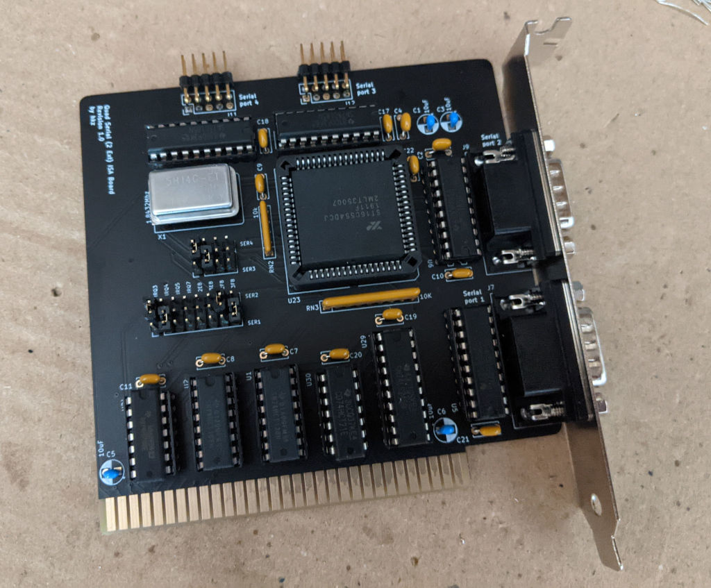
This 8-bit ISA board will provide 4 serial RS232 ports using a single 16C554 controller. 2 ports are exposed on an external bracket and 2 are on internal headers.
ISA QuadUART is an open-source printed circuit board by hkzlab, from the hkzlab/ISA_QuadUART2 repository on GitHub, published under the CC-BY-SA-4.0 licence. It is a 2-layer board of 104.1 × 102.9 mm with 42 parts on 168 nets, routed with 1,288 tracks and 36 vias.
It is built around the GD75232N, 74LS245SC and 74HCT138D, with the 74HCT32D among its other parts. Its parts include 17 capacitors, 11 connectors, 10 ICs and 1 crystal. It belongs with the interfaces and adapters and retro computing and games boards of this library.


This 8-bit ISA board will provide 4 serial RS232 ports using a single 16C554 controller.
Port 1 and 2 are exposed on the bracked as DB9 male connectors. Port 3 and 4 are internal.
IRQs will be shared between port 1/3 and port 2/4.
I take NO responsibility for what happens if you decide to build and use this card. Your computer might crash, catch fire or be destroyed in other nasty ways. You're encourauged to take what you deem fit from this, and use it in your projects!
This board is configured via two blocks of jumpers:
    .... SER4
    ....
    .... SER3
IIII2323
RRRREEFF
QQQQ8888
3457
........ SER2
........
........ SER1
The upper block will select the address for port 3 (first row) and port 4 (third row). To select an address, you need to bridge the middle row at the specified address with the top or bottom row (depending on which port you wish to assign that address).
The bottom block selects the address for ports 1 and 2, and the IRQs for ports 1/3 and 2/4. The principle is the same.
Default configuration is as follow:
    |... SER4
    ||..
    .|.. SER3
IIII2323
RRRREEFF
QQQQ8888
3457
|.....|. SER2
||....||
.|.....| SER1
Which will assign 0x3F8 to port 1, 0x2F8 to port 2, 0x3E8 to port 3 and 0x2E8 to port 4. Port 1/3 will get IRQ4 and port 2/4 will get IRQ3.
| Qty | Value | Footprint | References |
|---|---|---|---|
| 13 | 100nF | Capacitor_THT:C_Disc_D6.0mm_W2.5mm_P5.00mm | C2, C4, C7, C8, C9, C10, C11, C17, C18, C19, C20, C21, C22 |
| 4 | 10uF | Capacitor_THT:CP_Radial_D5.0mm_P2.50mm | C1, C3, C5, C6 |
| 4 | GD75232N | Package_DIP:DIP-20_W7.62mm_LongPads | U5, U6, U25, U26 |
| 2 | 74HCT138 | Package_DIP:DIP-16_W7.62mm_LongPads | U1, U2 |
| 1 | 1.8432Mhz | ISA_DualUART:Oscillator_DIP-14-8 | X1 |
| 1 | 10K | Resistor_THT:R_Array_SIP9 | RN3 |
| 1 | 10k | Resistor_THT:R_Array_SIP5 | RN2 |
| 1 | 16C554 | Package_LCC:PLCC-68_THT-Socket | U23 |
| 1 | 74HCT21 | Package_DIP:DIP-14_W7.62mm_LongPads | U30 |
| 1 | 74HCT32 | Package_DIP:DIP-14_W7.62mm_LongPads | U24 |
| 1 | 74LS245 | Package_DIP:DIP-20_W7.62mm_LongPads | U29 |
| 1 | ADDR | Connector_PinHeader_2.54mm:PinHeader_1x04_P2.54mm_Vertical | J5 |
| 1 | ADDR_IRQ | Connector_PinHeader_2.54mm:PinHeader_1x08_P2.54mm_Vertical | J2 |
| 1 | ISA BUS | skiselev_footprints:Conn_Edge_PCB_ISA8 | J1 |
| 1 | Serial 1 DB9 | Connector_Dsub:DSUB-9_Male_Horizontal_P2.77x2.84mm_EdgePinOffset7.70mm_Housed_MountingHolesOffset9.12mm | J7 |
| 1 | Serial 2 DB9 | Connector_Dsub:DSUB-9_Male_Horizontal_P2.77x2.84mm_EdgePinOffset7.70mm_Housed_MountingHolesOffset9.12mm | J9 |
| 1 | Serial 3 IDC | Connector_PinHeader_2.54mm:PinHeader_2x05_P2.54mm_Vertical | J12 |
| 1 | Serial 4 IDC | Connector_PinHeader_2.54mm:PinHeader_2x05_P2.54mm_Vertical | J11 |
| 1 | UART1_SEL | Connector_PinHeader_2.54mm:PinHeader_1x08_P2.54mm_Vertical | J3 |
| 1 | UART2_SEL | Connector_PinHeader_2.54mm:PinHeader_1x08_P2.54mm_Vertical | J4 |
| 1 | UART3_SEL | Connector_PinHeader_2.54mm:PinHeader_1x04_P2.54mm_Vertical | J8 |
| 1 | UART4_SEL | Connector_PinHeader_2.54mm:PinHeader_1x04_P2.54mm_Vertical | J13 |
The 41 most common of 42 parts.
It measures 104.1 × 102.9 mm and has 2 copper layers, 1.6 mm thick.
42 parts, built around the GD75232N, 74LS245SC, 74HCT138D and 74HCT32D. The full list of its parts is on this page, with links to each part's symbol and footprint where PCBKit's library has them.
From the hkzlab/ISA_QuadUART2 repository on GitHub, at the commit this page was made from: the board is ISA_QuadUART.kicad_pcb. PCBKit opens the board in the browser, with nothing to install.
Its repository publishes it under the CC-BY-SA-4.0 licence: you may reuse it on that licence's terms (keep the author's notice, and for a copyleft licence share your changes alike).


mudmin/AnotherMaker
This is where I will store code snippets for AnotherMaker Videos


leomil72/LM80C
A Z80-based homebrew computer withTMS9918, AY-3-8910, Z80 CTC, Z80 PIO, and Z80 SIO


b3rendsh/msxdos2s
MSXDOS smaller 16K/32K rom with IDE interface drivers and enhancements

skiselev/minimax8085-apu-ext
Arithmetic Processor and Extension Board for MiniMax 8085 SBC