4 layers340 × 210 mm
 mudmin/AnotherMaker258
This is where I will store code snippets for AnotherMaker Videos
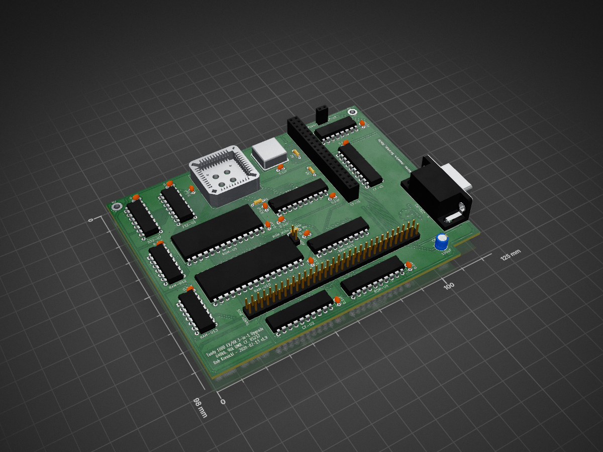
3-in-1 is an open-source printed circuit board by mudmin, from the mudmin/AnotherMaker repository on GitHub. It is a 2-layer board of 125 × 98 mm with 44 parts on 157 nets, routed with 1,590 tracks and 101 vias.
It is built around the 74LS245SC, GD75232N and 74LS00SC, with the 74LS139PC, 74LS32SC and AS6C4008-55PCN among its other parts. Its parts include 16 capacitors and 4 resistors.


This is forked from https://github.com/rkrenicki/Tandy-EX-HX-3in1 and this repo is primarily here in case his goes away for some reason.
This is a single expansion board designed for the Tandy 1000 EX and HX computers, to include the following upgrades:
This board is for the Tandy 1000EX and 1000HX computers only. It will not work in any other computer model as it is. You must remove any expansion cards already in the computer, this is designed to be a single-board upgrade and has no provisions to allow for any other expansion cards.
This board plugs into the Tandy PLUS interface, and takes up "Slot 2" on the rear of the computer. Please be careful to align the PLUS bus connector before pushing down, to avoid bending pins on the computer. Secure the backplate to the computer with two screws. The IDE BIOS will automatically start and boot directly to the CF card on 1000EX machines. 1000HX loads a boot menu by default, and you will need to press F4 to load the IDE BIOS. If you want to bypass the Tandy DOS ROM and boot menu, run "SETUPHX" and change the "Primary Start-up Device" to "DISK" and press F1 to save.
This board has no configuration jumpers and is designed to be plug-and-play. The only jumper is to enable programming the ROM. Install the jumper to flash the XT-IDE BIOS, otherwise the jumper should be removed. All assembled boards and kits sold by me come with a pre-programmed ROM, and this jumper should be left empty.
The board is hardwired with these memory locations/ports:
SRAM:  0x0000-0x5FFF, 0xC800-0xDFFF
UART:  0x3F8, IRQ 4
IDE:   0x300
ROM: 0xC000-0xC7FFAll functions of the board are independent, no parts are shared between functions. If you do not want to use a specific function, you can safely omit any parts referenced with the function in the name (such as "232" for RS232).
Recommended assembly order: (Shortest to tallest)
NOTE: Please take careful note of part orientation. To optimize some trace routing, not all chips are oriented in the same direction. 232-U6, 232-U8, and RAM-U11 are all opposite oritentation than the other horizontal chips. Installing these backwards will destroy the chips. Pay special attention to 232-U8's socket, it must be installed with the "Pin 1 Arrow" installed facing towards the left of the board. 232-OSC1 is installed "upside down", with the squared corner facing the upper right.
| Quantity | Ref(s) | Mouser Part Number | Digikey Part Number | Description |
|---|---|---|---|---|
| 1 | BUS1 | 200-CES13101SD See Note2 Below | SAM1084-31-ND See Note2 Below | 2x31 2.54mm Header Socket |
| 1 | CF-J1 | 517-8540-4500PL | 2x20 2.54mm Header Socket, 11mm height. | |
| 4 | R1 through R4 | 603-CFR-12JT-52-10K | 10kOhm Resistor | |
| 16 | C1 through C16 | 594-K104M15X7RF53L2 | 0.1uF Multilayer Ceramic Capacitor, 2.5mm Lead Spacing | |
| 1 | CP1 | 647-RNU1C101MDS1 | 100uF 16V Polymer or Electrolytic Capacitor, 2.5mm Lead Spacing | |
| 1 | 232-OSC1 | 774-MXO45HS-3C-1.8 | 110-MXO45HS-3C-1M843200-ND | 1.8432Mhz 1/2-size Oscillator |
| 1 | 232-P2 | 806-K22X-E9P-N-99 | 2092-K22X-E9P-N-ND | DE9 Male Right Angle Connector |
| 2 | 232-P2 Screw | 571-5207953-3 | SFSO4401NR-ND | Jackscrew for DE9 connector |
| 1 | 232-U6 | 595-GD75232N | 296-GD75232N-ND | GD75232N RS232 Driver |
| 2 | 232-U7, 232-U9 | 595-SN74LS138N | 296-1639-5-ND | 74LS138 3-to-8 Line Demux |
| 1 | 232-U8 | 701-ST16C550CJ44TR-F | 1016-1259-5-ND | 16550/16C550 UART in PLCC-44 Package |
| 1 | 232-U8 Socket | 517-8444-11B1-RK-TP | 3M4411B1-ND | PLCC-44 Through Hole Socket |
| 1 | CF-J2 | 200-CES10101TD | 1x2 2.54mm Header Socket | |
| 1 | CF-U1 | 595-SN74LS139AN | 296-1640-5-ND | 74LS139 Dual 2-to-4 Demux |
| 2 | CF-U2, ROM-U4 | 595-SN74LS688N or 595-SN74F521N | 296-1667-5-ND | 74LS688 or 74F521 8-bit Comparator |
| 2 | CF-U3, RAM-U11 | 595-SN74LS245N | 296-1655-5-ND | 74LS245 Tri-state Bus Transciever |
| 1 | RAM-U10 | 913-AS6C4008-55PCN | 1450-1027-ND | AS6C4008-55PCN 4mbit (512k x 8) Static RAM |
| 1 | RAM-U12 | 595-SN74LS00N | 296-1626-ND | 74LS00 Quad NAND Gate |
| 1 | RAM-U13 | 595-SN74LS32N | 296-1658-5-ND | 74LS32 Quad OR Gate |
| 1 | ROM-U5 | 556-AT28C64B15PU | AT28C64B-15PU-ND | 28C64 64k x 8 EEPROM |
| 1 | ROM-U5 Socket | 517-4828-6000-CP | ED3052-5-ND | 28-pin Wide DIP Socket |
| 1 | CF-IDE Adapter | n/a | n/a | CF to IDE Adapter from eBay or AliExpress (See note below) |
Note: All 74LSxx series logic ICs can be substituted with any family with "LS" or "T" in the name, such as ALS, ACT, AHCT, or HCT among others.
Note2: For the BUS1 Connectors, I have many of these left over from my last order of custom connectors. You can buy them for $1/ea plus shipping. Even for one, it is far cheaper than the $13 that Mouser wants. Please email tandy.3in1@gmail.com to order.
This board uses the XT-IDE Universal BIOS. I have included pre-configured images for 2.0.0B3 r602 (latest version as of the time of writing this). The 3in1BIOS-8088.zip will work on any EX or HX computer, and is the version that I preload on assembled boards and kits. I have also included a V20 Enhanced version for any EX/HX that has an NEC V20 (or clone) installed. This enhanced version will roughly double your disk speed, but only works on V20 machines.
This board is designed a specific version of a CF-IDE adapter. They are widely available on eBay and AliExpress. It bears the mark of "IDE to CF Ver.D2". It can generally be identified by the metal cover over the CF card connector. I do not have a link to any one specific vendor or listing, but if the adapter includes the metal backplate and has a metal cover over the CF slot, then it should be correct.
The CF adapter does also need a few modifications, please refer to the "IDE Adapter Modifications.pdf" for details. It also has photos of the adapter for reference to buy the proper adapter.
If you have any questions, feel free to join the Discord server below and ask in the #tandy-3in1-support channel.
I have started a Discord server for more real-time technical support, as well as discussion for my various projects in progress. You can follow this link to join: https://discord.gg/QmFssyXnQt
This project is licensed under the Creative Commons - Attribution - ShareAlike 3.0 License
This board was derrived from works by, uses design elements from, or contains sofware writen by the following:
| Qty | Value | Footprint | References |
|---|---|---|---|
| 16 | 0.1uF | Capacitor_THT:C_Disc_D3.0mm_W2.0mm_P2.50mm | C1, C2, C3, C4, C5, C6, C7, C8, C9, C10, C11, C12, C13, C14, C15, C16 |
| 4 | 10K | Resistor_THT:R_Axial_DIN0204_L3.6mm_D1.6mm_P5.08mm_Horizontal | R1, R2, R3, R4 |
| 2 | 74ALS138 | Package_DIP:DIP-16_W7.62mm | 232-U7, 232-U9 |
| 2 | 74LS245 | Package_DIP:DIP-20_W7.62mm | CF-U3, RAM-U11 |
| 2 | 74LS688 | Package_DIP:DIP-20_W7.62mm | CF-U2, ROM-U4 |
| 2 | MountingHole | MountingHole:MountingHole_2.7mm_M2.5_ISO7380_Pad | H1, H2 |
| 1 | 1.8432MHz | Oscillator:Oscillator_DIP-8 | 232-OSC1 |
| 1 | 100uF | Capacitor_THT:CP_Radial_D5.0mm_P2.50mm | CP1 |
| 1 | 16C550 | Package_LCC:PLCC-44_THT-Socket | 232-U8 |
| 1 | 28C64 | Package_DIP:DIP-28_W15.24mm | ROM-U5 |
| 1 | 74LS00 | Package_DIP:DIP-14_W7.62mm | RAM-U12 |
| 1 | 74LS139 | Package_DIP:DIP-16_W7.62mm | CF-U1 |
| 1 | 74LS32 | Package_DIP:DIP-14_W7.62mm | RAM-U13 |
| 1 | AS6C4008-55PCN | Package_DIP:DIP-32_W15.24mm | RAM-U10 |
| 1 | CF Interface | Connector_PinSocket_2.54mm:PinSocket_2x20_P2.54mm_Vertical | CF-J1 |
| 1 | CF Power | Connector_PinSocket_2.54mm:PinSocket_1x02_P2.54mm_Vertical | CF-J2 |
| 1 | GD75232 | Package_DIP:DIP-20_W7.62mm | 232-U6 |
| 1 | ROM Write Enable | Connector_PinHeader_2.54mm:PinHeader_1x02_P2.54mm_Vertical | ROM-JP1 |
| 1 | SERIAL | Connector_Dsub:DSUB-9_Male_Horizontal_P2.77x2.84mm_EdgePinOffset7.70mm_Housed_MountingHolesOffset9.12mm | 232-P2 |
| 1 | TANDY_BUS | Tandy-IO:TANDY-PLUS-BUS | BUS1 |
The 42 most common of 44 parts.
It measures 125 × 98 mm and has 2 copper layers, 1.6 mm thick.
44 parts, built around the 74LS245SC, GD75232N, 74LS00SC and 74LS139PC. The full list of its parts is on this page, with links to each part's symbol and footprint where PCBKit's library has them.
From the mudmin/AnotherMaker repository on GitHub, at the commit this page was made from: the board is tandy-3-in-1/3-in-1.kicad_pcb and its schematic Kicad 8/Kicad 8/Kicad 8.kicad_sch. PCBKit opens the board in the browser, with nothing to install.
Its repository states no licence, so its author keeps all rights: ask mudmin before reusing the design.

tergav17/Z80-MegaMapper
Z80 interposer board providing extended memory and I/O instruction mapping


misterblack1/tandy1000ex-hx-ram
Tandy 1000EX/HX RAM Expansion Board

CPTforever/8088-MicroATX-Computer
A 8088 based, IBM 5150 like computer compatible with the MicroATX motherboard form factor.

sladek/SBC_8080_ECB
This is my attempt to build a single-board microcomputer based on the Intel 8080 CPU. It contains the following features:

The-Invent0r/8-bit-Computer-PCB
These are the KiCAD files for my 8-Bit Computer.
