


2 layers297.2 × 180.3 mm

MSXDOS smaller 16K/32K rom with IDE interface drivers and enhancements
Malt is an open-source printed circuit board by b3rendsh, from the b3rendsh/msxdos2s repository on GitHub. It is a 2-layer board of 99.7 × 64.1 mm with 35 parts on 106 nets, routed with 966 tracks and 105 vias.
It is built around the 74HCT04D, 74HCT138D and 74HCT32D. Its parts include 6 capacitors, 5 resistors, 5 ICs, 3 connectors and 2 switches. It belongs with the retro computing and games boards of this library.


MSX 8255 PPI IDE board that is based on the Eurocard Bus DiskIO V3 PPIDE design for retrocomputers.
It uses the same 8255 PPI chip as the MSX BEER interface but the IDE control signals are implemented in a more robust way.
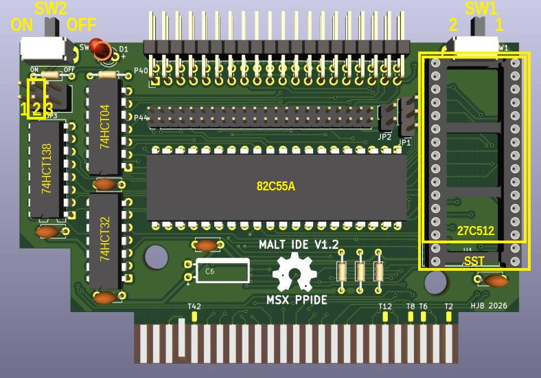
[!CAUTION] If the SW1 switch is mounted then the JP1 jumper should not be used.
Only toggle the SW1 switch (right side) when the MSX computer is off.The SW2 switch (left side) can be toggled when the MSX computer is on.
A basic understanding of the MSX (disk) system, soldering skills and knowledge of retro computer electronics is required to build and use this cart.
Choose the type of IDE connector
Choose flash ROM or EEPROM
SST flash ROM (default)
The cart can be used with 128K, 256K or 512K SST (or other JEDEC compatible) flash ROM.
Use a jumper (JP1) or SPDT switch (SW1) to switch between two ROM banks.
Don't populate the PCB with both JP1 and SW1 or else you can create a short circuit!
The switch or jumper should only be toggled when the MSX computer is off!
W27C512 EEPROM
Make sure to place the 28-pin chip correctly in the 32-pin socket. See pictures.
Flash the disk ROM with an external programmer like the T48.
A standard 32KB disk ROM image should start at EEPROM address 0x4000!
The ROM bank switch/jumper will have no function.
Select an I/O address range with jumper JP3
1: 0x1C-0x1F
2: 0x34-0x37 (default)
3: 0x3C-0x3F
The MSX-DOS software driver will try to autodetect the selected I/O address.
Select disk media type to use with the cart
Compact Flash (default)
There are CF to IDE adapters for 40 pin or 44 pin IDE connectors. The front of the adapter should point to the backside of the MSX cart! See pictures.
Some of the 40 pin CF adapters have pin 20 blocked. You can still use them if you drill a hole and connect a dupont wire between the CF card power conector (LP4) and jumper JP2 +5V pin. See pictures.
Classic 2,5" notebook harddisk
This type of disk uses a 44-pin connector. It is not recommended to power the harddisk via the MSX! Instead use an external power supply and a custom built adapter cable.
Classic 3,5" harddisk
This type of disk uses a 40-pin connector. A 40-pin flat cable may have pin 20 blocked. Use an external molex power adapter (or old ATX power supply).
Other ATA/IDE disks
E.g. using SD to IDE adapter or SATA to IDE. These options are not tested yet.
The LED on the cart should light up whenever there is disk activity.
You can use the flask program to flash a disk image to the selected ROM bank.
If you don't have a 2nd disk system then you can load CXDOS1D.BIN from tape to flash the ROM. In this scenario the disk media should have a valid MSX FAT partition with flask.com and disk image file. The MSX tape input can be used with an android phone and msx2cas app to load the bin file. Alternatively you can also a convert a bin file to a wav file with openMSX and play the wav on a suitable device.
Schematics and Kicad project files are provided so you can make changes if you want to.
The 8255 PPI chip has been used for different types of interfaces. E.g. with a few changes you can create a multi-i/o board or a bidirection printer port. The unused pins on the cart's edge connector have small solder pads to facilitate this type of experiments.
The cart should fit in a Konami type case with some cutouts for the switches and ic's if sockets are used.
| Qty | Value | Footprint | References |
|---|---|---|---|
| 10 | TestPoint | Connector_Wire:SolderWirePad_1x01_SMD_1x2mm | T1, T2, T3, T6, T7, T8, T9, T12, T42, T49 |
| 5 | 100nF | Capacitor_THT:C_Disc_D4.7mm_W2.5mm_P5.00mm | C1, C2, C3, C4, C5 |
| 4 | 10K | Resistor_THT:R_Axial_DIN0204_L3.6mm_D1.6mm_P7.62mm_Horizontal | R2, R3, R4, R5 |
| 2 | PIN_1x3 | Button_Switch_THT:SW_Slide_SPDT_Angled_CK_OS102011MA1Q | SW1, SW2 |
| 1 | + | LED_THT:LED_D3.0mm | D1 |
| 1 | 100uF | msx:CP_lying | C6 |
| 1 | 330 | Resistor_THT:R_Axial_DIN0204_L3.6mm_D1.6mm_P7.62mm_Horizontal | R1 |
| 1 | 74HCT04 | Package_DIP:DIP-14_W7.62mm | U4 |
| 1 | 74HCT138 | Package_DIP:DIP-16_W7.62mm | U5 |
| 1 | 74HCT32 | Package_DIP:DIP-14_W7.62mm | U3 |
| 1 | 82C55A | Package_DIP:DIP-40_W15.24mm | U2 |
| 1 | Conn_01x02 | Connector_PinHeader_2.54mm:PinHeader_1x02_P2.54mm_Vertical | JP2 |
| 1 | Conn_02x03 | Connector_PinHeader_2.54mm:PinHeader_2x03_P2.54mm_Vertical | JP3 |
| 1 | Conn_02x22 | Connector_PinHeader_2.00mm:PinHeader_2x22_P2.00mm_Vertical | P44 |
| 1 | MSX_SLOT_CON | msx:Cart_Konami | CN1 |
| 1 | PINHD-02x20 | Connector_PinHeader_2.54mm:PinHeader_2x20_P2.54mm_Horizontal | P40 |
| 1 | PIN_1x3 | Connector_PinHeader_2.54mm:PinHeader_1x03_P2.54mm_Vertical | JP1 |
| 1 | SST39SF0X0 | Package_DIP:DIP-32_W15.24mm_Socket | U1 |
It measures 99.7 × 64.1 mm and has 2 copper layers, 1.6 mm thick.
35 parts, built around the 74HCT04D, 74HCT138D and 74HCT32D. The full list of its parts is on this page, with links to each part's symbol and footprint where PCBKit's library has them.
From the b3rendsh/msxdos2s repository on GitHub, at the commit this page was made from: the board is hardware/malt/malt.kicad_pcb and its schematic hardware/malt/malt.kicad_sch. PCBKit opens the board in the browser, with nothing to install.
Its repository states no licence, so its author keeps all rights: ask b3rendsh before reusing the design.

leomil72/LM80C
A Z80-based homebrew computer withTMS9918, AY-3-8910, Z80 CTC, Z80 PIO, and Z80 SIO


flypie/Gigatron
This is a version of the files from https://gigatron.io/ altered to work on a vanilla KiCAD 5.1.6. Changes are minimal in the schematic and PCB, layout has only been changed where dimensions or orientations changed as a…


