

4 layers110 × 90 mm

 HeyPCB/knuckle1
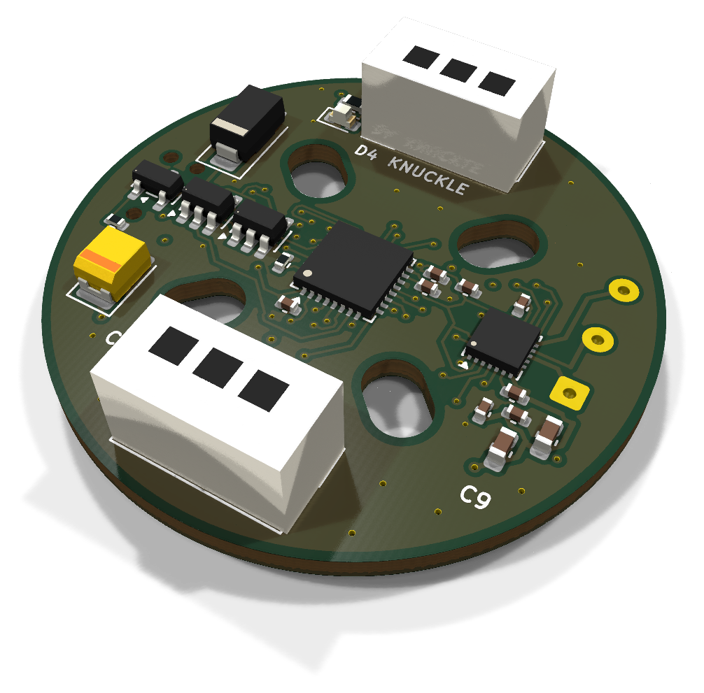
35 mm round FOC driver for a GBM2804 gimbal motor that answers on the Open Duck Mini's servo bus as an STS3215. 6-layer KiCad 10 board plus printed standoff, cover and horn adapter.
Knuckle is an open-source printed circuit board by HeyPCB, from the HeyPCB/knuckle repository on GitHub, published under the CERN-OHL-S-2.0 licence. It is a 6-layer board of 25.9 × 16.8 mm with 45 parts on 51 nets, routed with 589 tracks and 67 vias.
It is built around the STM32G431KBU6, SN74LVC1G125DBVR-TP and SN74LVC1G126DBVR-TP, with the DRV8311HRRWR, MT6701QT-STD and CL05B104KB54PNC among its other parts. Its parts include 17 capacitors, 13 resistors, 5 ICs, 4 diodes and 4 connectors. It belongs with the robots and motor control boards and the STM32 boards of this library.


A 35 mm round FOC driver that bolts to a GBM2804 gimbal motor and answers on the Open Duck Mini's servo bus as an STS3215.
Part of HeyPCB's open robot boards. Designed end to end with the HeyPCB method on
KiCad 10 (headless pipeline, Freerouting 2.4.1); every number below is measured on the files in this repository.
Mentions of ./run.sh, docs/rules/, blocks/ or parts/ refer to the heypcb-kicad SDK that produced them.
| Layers | Outline | Parts | Nets | Connections routed | Vias | ERC errors | DRC errors / unconnected / parity |
|---|---|---|---|---|---|---|---|
| 6 | 35 mm round | 45 | 34 | 121 -> 0 open | 67 | 0 | 0 / 0 / 0 |
Not fabricated, assembled or powered.
| KiCad project | kicad/ |
| Gerbers (unzipped and zipped), BOM, CPL, STEP, schematic PDF | fab/ |
| Printed parts (STEP/STL), CadQuery source, fit report | cad/ |
| Renders | top, bottom |
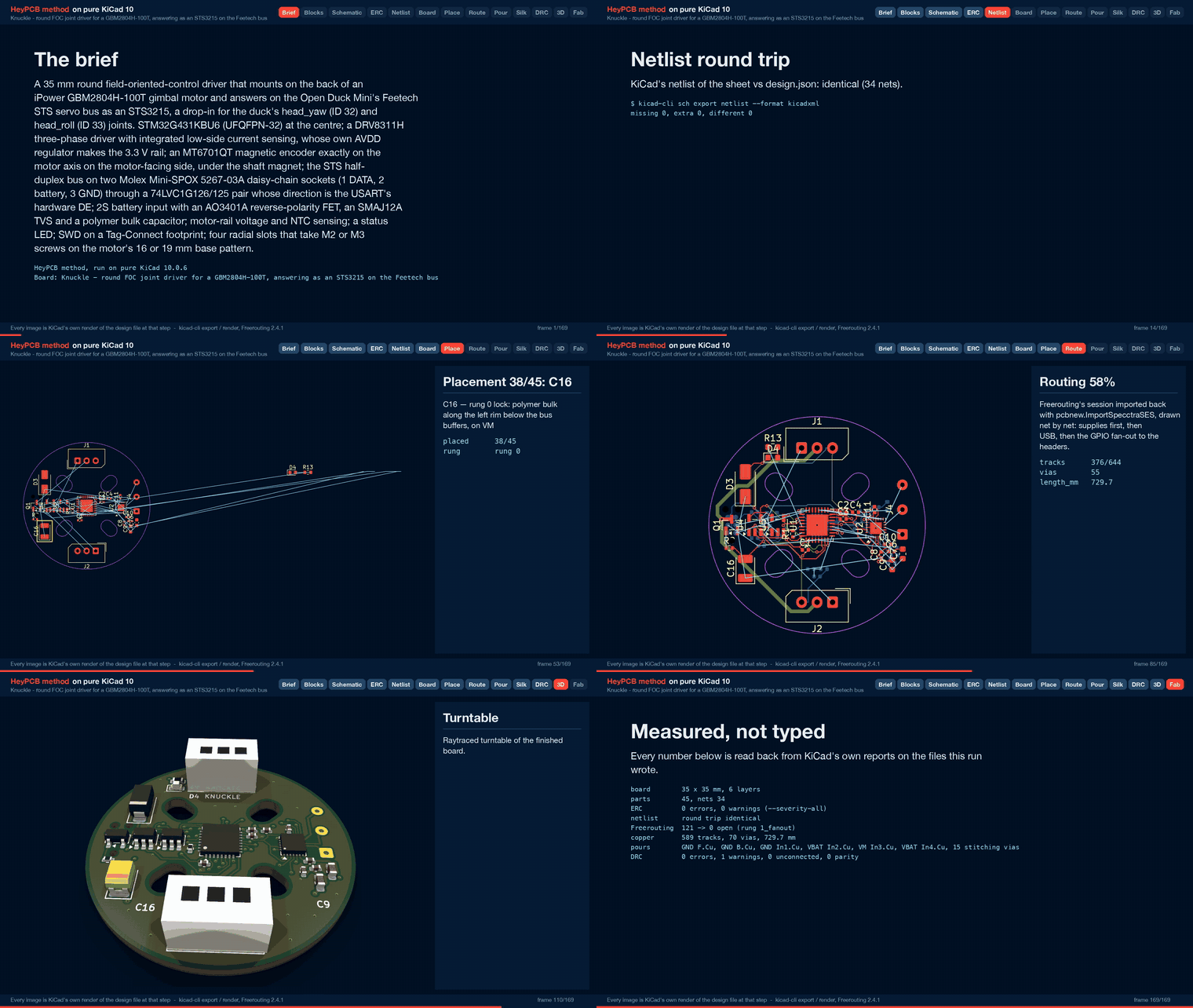
| Design process, every step as KiCad rendered it | media/design-process.mp4 |
Knuckle is a 35 mm round field-oriented-control (FOC) driver that mounts on the back of an iPower
GBM2804H-100T gimbal motor and answers on the Open Duck Mini's Feetech STS servo bus as an STS3215
(model 777). It is meant as a drop-in for the duck's head_yaw (ID 32) and head_roll (ID 33)
joints. It was designed with the HeyPCB method on KiCad 10 (the headless heypcb-kicad pipeline,
KiCad 10.0.6, routed by Freerouting 2.4.1) from the brief in board.json, following the research
spec in robots/research/actuator/spec.md.
It has not been fabricated, assembled or powered, and its firmware is not written. The STS3215
emulation below is what that firmware must do; none of it exists yet. Every gate number below is
read from the final run's report.json. What this README says about copper, pours, pads and
silkscreen was read from kicad/knuckle.kicad_pcb with KiCad 10.0.6's pcbnew, and every
mechanical number was measured on the solids by cad/parts.py (cad/fit.json).
Numbers marked (est.) are estimates or come from the spec; they are not measurements.
The spec's answer, which this board follows: a 2804-class gimbal motor on a 2S pack cannot replace an STS3215 in a duck leg, direct or geared. The numbers are the spec's (sections 0 and 2; model outputs and MuJoCo static torques, not bench measurements):
| Stall torque | Speed | Note | |
|---|---|---|---|
| STS3215, 7.4 V (datasheet) | 1.91 N·m | 5.45 rad/s | what the duck's legs use |
| GBM2804H-100T, direct drive, 7.4 V | 0.047 N·m (est.) | 110 rad/s (est.) | 2.5 % of the STS3215; continuous rating 0.025-0.034 N·m (vendor's load torque) |
| GBM2804H-100T + 36:1 planetary | 1.26 N·m (est.) | 3.1 rad/s (est.) | still short of the STS3215 on both |
Static load, knee (single support) | 1.02-1.08 N·m | ||
Static load, hip_roll (single support) | 0.89-0.92 N·m | ||
Static load, neck_pitch / head_pitch | 0.053-0.075 N·m | needs at least 1:5 gearing (est.) | |
Static load, head_yaw / head_roll | 0.000 / 0.001-0.016 N·m | within the direct-drive motor's continuous rating |
At 7.4 V every gimbal winding the spec checked (5-11 Ohm) is voltage-limited to about 1.2-2.7 W of
mechanical power (est.), against the STS3215's 2.6 W (datasheet) to 4.5 W (identified model). So
v1 is a direct-drive head actuator: the MT6701 under the shaft magnet is the absolute joint
encoder, with no gearbox, no backlash and no second encoder, and the duck's runtime keeps working
unchanged because the board answers as model 777 at the same IDs and registers. The ten leg
joints, neck_pitch and head_pitch stay on STS3215.
| The spec says | On the board | Why |
|---|---|---|
| 3V3 from the DRV8311's AVDD (TTL variant) or an AP63203 buck | AVDD | The load is the MCU, the MT6701, CSAREF, the bus buffers and the LED: about 54 mA (the spec's 68 mA budget without the external encoder v1 does not have; est.), inside AVDD's 100 mA. AVDD then dissipates (8.4 - 3.3) V x 54 mA = 0.28 W in the driver (est.); the spec puts the driver's total at 0.76 W or less with 68 mA, about 40-45 C above ambient inside a cover (est.). The buck would add a 4 x 4 mm inductor and about 55 mm² of courtyard (spec: 425 vs 370 mm²) to a board that did not route on four layers without it. Neither margin is measured: see Check these before ordering |
| nSLEEP "pull it up" | 100k from VM, clamped by an MM5Z5V1 5.1 V zener | Sleep turns AVDD off (TI SLVSFN2B 8.4.1.1), and nSLEEP has a 230-300k internal pull-down. Pulled up from AVDD, the part would never wake. 100k from VM gives about 4.2 V at VM 6.0 V (VIH 1.65 V max); the zener keeps the pin under its 5.5 V recommended maximum up to the TVS's 19.9 V clamp |
| SLEW 47k to AGND (75 V/us) | SLEW tied to AGND (35 V/us) | One part and one net fewer on the tightest spot of the board, and the slowest, quietest edge. Cost: about 33 mW of switching loss per phase at stall (est.) |
| GAIN with a 47k footprint for a geared v2 | GAIN left open (1 V/A), no footprint | At 1 V/A the CSAs read about ±1.4 A around 1.65 V, against this motor's 0.92 A peak stall current (est.) |
| 47 uF / 16 V polymer, 3528 | 22 uF / 25 V polymer tantalum T521B226M025ATE100 (C696813, 100 mOhm) | The live catalogue's B-case rows at 16 V and up offered 47 uF only as MnO2 tantalum (CA45), a poor partner for a low-impedance Li-ion pack. Table 8-1 of the datasheet asks for at least 10 uF on VM; the board has 22 uF + 2 x 10 uF |
| 4 layers | 6 layers | Measured on 2026-10-02: on 4 layers (F / In1 GND / In2 / B) three placements routed 122 -> 8, 122 -> 4 and 121 -> 5 open, every time into the 0.4 mm-pitch driver whose escape lanes the screw slots squeeze. The full sequence is in docs/rules/pipeline.md |
| 4 x Ø2.2 mm M2 holes on Ø16 / Ø19, turned 45° | 4 radial slots, 3.4 mm wide, screw centres from r = 8.0 to 9.5 mm on the diagonals | The base pattern is not confirmed (spec 2.4). The slots take M2 or M3 on the 16 mm pair (r = 8.0), the 19 mm pair (r = 9.5) and a 12 mm square (r = 8.49), turned 45° so no screw lands under a bus socket. A 12 mm diameter pattern (r = 6.0) does not fit them. Measure before ordering |
| Phase tracks 0.2-0.3 mm (this board's request; spec 4.7 accepts 0.2 mm) | MOTOR class 0.25 mm, all on F.Cu; one 2.26 mm stretch of PHASE_B at 0.187 mm | 0.25 mm is the widest track that enters the DRV8311's 0.2 mm OUTx pads at 0.4 mm pitch. The 0.187 mm stretch is the router's, beside pin 11 (see Phase current and copper): 0.71 A on 1 oz outer, against 0.65 A RMS at an 8.4 V stall |
| Motor phase pads 3 x 1.5 x 2.5 mm (est.) | KiCad's 1 x 3 solder-wire land (SolderWire-0.15sqmm_1x03_P4mm_D0.5mm_OD1.5mm) | Three plated holes at 4 mm pitch at the right rim, in the order of the driver's OUTC/B/A pins, so the phases fan out on F.Cu without crossing. Marked do-not-populate (nothing to buy) |
| RS-485 / CAN as stuffing options; a 6-pin port for a second encoder | Not on v1 | Both are for a geared v2. A transceiver's 50+ mA does not fit AVDD's budget (it needs the buck and, for CAN, a crystal), and the board already needed six layers. PA11 / PA12 (FDCAN1) are left unconnected for a CAN variant |
| Pin plan: enable PB5, sense PA4 / PA6 / PA7, VBUS PB0, nFAULT PB7, LED PF1 | enable PB0, sense PA5 / PA6 / PA7, VM PA4, NTC PA0, nFAULT PF0, LED PB6 | The MCU is turned 90° so its ADC and enable pins face the driver; the pins were moved to the ones on that edge. All three phase currents stay on ADC2, as SimpleFOC's low-side sensing on the G4 wants |
| J1 "IN", J2 "OUT" | Front silkscreen KNUCKLE at J1 and STS BUS at J2 | The sockets are wired in parallel, so neither is an input. The board name had no other free spot on the front |
The MCU pins (read back from the board's U1 pads; functions from the KiCad symbol's own alternates):
| Pin | Net | Function |
|---|---|---|
| PA8 / PA9 / PA10 | PWM_A / PWM_B / PWM_C | TIM1_CH1 / CH2 / CH3 -> DRV8311 INHA / INHB / INHC |
| PB0 | DRV_EN | DRV8311 INLA + INLB + INLC. 100k pull-down: all three half bridges stay Hi-Z while the MCU is in reset |
| PA5 / PA6 / PA7 | ISENSE_A / B / C | ADC2_IN13 / IN3 / IN4 <- SOA / SOB / SOC |
| PA4 | VM_SENSE | ADC2_IN17, VM x 22 / 122 (8.4 V reads 1.51 V) |
| PA0 | TEMP | ADC1_IN1, 10k NTC (B 3380) under a 10k pull-up |
| PF0 | NFAULT | DRV8311 nFAULT, 5.1k to 3V3 |
| PA1 / PA2 / PA3 | BUS_DE / BUS_TX / BUS_RX | USART2_DE / TX / RX. DE has a 100k pull-down, so the board never drives the bus in reset |
| PA15 / PB3 / PB4 | ENC_CS / ENC_CLK / ENC_DO | SPI1_NSS / SCK / MISO -> MT6701 CSN / CLK / DO. PA15 comes out of reset with a pull-up, so CSN idles high |
| PA13 / PA14 / NRST | SWDIO / SWCLK / NRST | Tag-Connect. SWO is left open: PB3 is the encoder clock |
| PB6 | LED_STAT | red LED through 1k |
| PB8 | BOOT0 | 10k pull-down: boots from flash |
| PF1, PA11, PA12, PB5, PB7 | none | not connected |
Phase current, from the spec's per-phase resistance (Rs = 5.292 Ohm, ST motor profiler) at the voltage-limited stall, where SVPWM puts VM / sqrt(3) across each phase (est.):
| Pack | Peak | RMS | DC into the bridge |
|---|---|---|---|
| 7.4 V (nominal 2S) | 0.81 A | 0.57 A | 0.70 A |
| 8.4 V (full 2S) | 0.92 A | 0.65 A | 0.79 A |
The DC column is the winding's VM² / (2 Rs) divided by VM: 5.2 W at 7.4 V and 6.7 W at 8.4 V. A 39 g motor cannot hold that; the spec asks the firmware for an I²t limit above about 0.3 A.
Track ratings by IPC-2221 at a 10 C rise (heypcb-kicad's route.ipc2221_amps):
| Width | 1 oz outer | 0.5 oz inner | 1 oz inner |
|---|---|---|---|
| 0.187 mm | 0.71 A | 0.21 A | 0.36 A |
| 0.225 mm | 0.81 A | 0.25 A | 0.41 A |
| 0.25 mm (MOTOR class) | 0.88 A | 0.27 A | 0.44 A |
| 0.3 mm (VM class) | 1.00 A | 0.30 A | 0.50 A |
| 0.6 mm (VBAT class) | 1.65 A | 0.50 A | 0.83 A |
Where the copper ran:
phase_lane_outer_only) keeps the phases on outer copper. On the route before it, PHASE_C took 6.8 mm of In2, where 0.25 mm carries 0.27 A at 0.5 oz.Not written. From spec section 5; register facts are cited there by file and line.
FF FF ID LEN INSTR P... CHK with CHK = ~(ID + LEN + INSTR + sum P) & 0xFF; drop bad checksums. Answer only its own ID, and broadcast (254) only in SYNC_READ slots. Honour Return Delay Time (reg 7) and Response Status Level (reg 8).set_kps SYNC_READs register 22 from all 14 IDs and fails if any one is silent.configure_motor.py sets it); baud at 6 (at least 0 = 1 M); P / D / I at 21 / 22 / 23; mode 33 (0 = position); torque enable 40 (0 = INLx low, bridge Hi-Z); goal position 42 and present position 56 (0-4095 from the MT6701's 14 bits >> 2 plus the homing offset at 31; 2048 = 0 rad; sign-magnitude in bit 15); present speed 58 (steps/s, bit 15 sign); load 60 (bit 10 sign); voltage 62 (0.1 V, from VM_SENSE); temperature 63 (from the NTC); current 69; limits 9 / 11 / 13-15 / 16 / 48; lock 55; acceleration and max velocity 41 / 84 / 85 accepted.tau = clamp(P x 0.166 x (7.4 x 1.178 / 2.479) x (q_ref - q) - 0.56 x omega - D-term, ±tau_max), with q_ref slew-limited to 5.29 rad/s, then Iq = tau / Kt. The motor's 0.03-0.047 N·m saturates it: at P = 8 the head is stiff only within about ±0.4° (est.).BLDCDriver3PWM(PA8, PA9, PA10, PB0), LowsideCurrentSense(1 V/A, PA5, PA6, PA7), MagneticSensorMT6701SSI(PA15), 7 pole pairs, 25 kHz centre-aligned PWM, sensor alignment stored in flash.Final run of 2026-10-02, ./run.sh --board boards/knuckle with media, from report.json:
| Gate | Result |
|---|---|
| Composition | 9 block instances -> 45 parts, 34 nets, 17 no-connects |
Part binding (lcsc_pinned.json) | 43 of 45 parts bound to an LCSC number, 0 unsourced, 0 identity conflicts. J3 (the Tag-Connect footprint) is not in the BOM, and J4 (the motor solder holes) is do-not-populate: there is nothing to buy for either. 11 distinct Extended parts, about $33 in JLC loading fees |
ERC (kicad-cli sch erc --severity-all) | 0 errors, 0 warnings |
| Netlist round trip | identical, 34 nets |
| Freerouting, rung 1, fanout on (kept) | 121 -> 0 open in 20.7 s, DRC score 0, 55 vias |
| Freerouting, rung 1, fanout off (measured for comparison) | 121 -> 1 open in 41.5 s, DRC score 1, 49 vias |
| Copper | 589 tracks, 55 routing vias, 729.7 mm of track (F.Cu 232.3, In2 107.7, In3 118.7, In4 113.4, B.Cu 157.7). No class was narrowed. After the import 14 segments were widened to their class width and 39 kept narrower where the class width would not clear another net (PHASE_B's 0.187 mm and VM's 0.225 mm among them) |
| Pours (only after a measured 0 open) | GND on F.Cu, In1 and B.Cu; VBAT on In2 and In4; VM on In3 (board.pours); 15 stitching vias (70 vias in all); 0 open after the pour, after stitching and at the end; no island-repair vias |
| Silkscreen | 3 words and the 6 back title lines placed; 11 designators re-seated and 31 hidden where nothing fit; 3 stitching vias displaced; nothing clipped. The STAT and MOTOR words did not land |
DRC (--severity-all --schematic-parity, KiCad 10.0.6) | fresh, 0 errors, 0 unconnected, 0 parity, 1 warning |
DFM (jlcpcb_6layer) | 0 errors, 1 warning (142 stock-footprint silk strokes at 0.12 mm; the fab prints them at its 0.15 mm minimum) |
| Fab gate | ready, no blockers; the JLC CPL corrected 19 rotations |
silk_over_copper: one stroke of D3's (the TVS's) front footprint silk crosses J3's NPTH alignment hole at (4.72, 14.96). The fab clips it.fab/knuckle.step has no body for J1 and J2. cad/parts.py stands in their F.Fab outline (9.9 x 4.9 mm) at the catalogue row's 5.9 mm height.Positions are in mm from the top-left corner of the board's 35 x 35 mm square, +y down; the motor axis is at (17.5, 17.5).
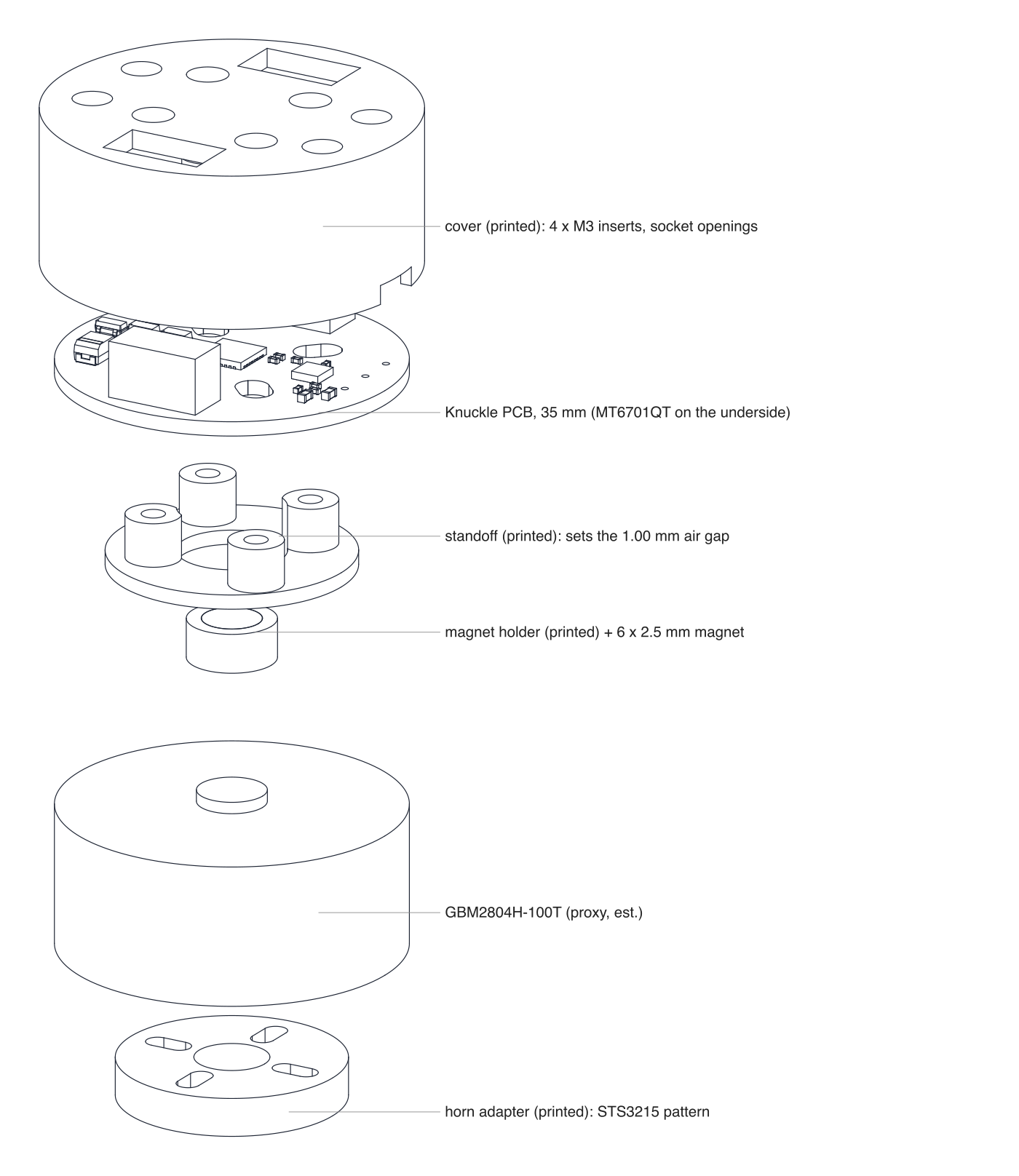
cad/parts.py (CadQuery 2.8, OCP, trimesh) builds four printed parts around the board's real STEP (fab/knuckle.step, solids named by reference) and the real STS3215 horn (STS3215_03a.step from SO-ARM100), and measures the fit on the solids. Frame: z = 0 is the motor's base (stator) face, +z toward the board. The motor itself (15 mm tall, Ø35, a Ø7 shaft stub protruding 1.2 mm) is the spec's (est.); see Check these before ordering.
| Part | What it is | Measured fit (fit.json) |
|---|---|---|
| Magnet holder | Cup pressed on the shaft stub: OD 9.0, bore 6.98 x 1.0 deep, floor 0.6, pocket Ø6.05 x 2.5 for the 6 x 2.5 mm diametric magnet. Print in PETG, or turn in brass or aluminium; never steel | Rides from z 0.2 to 4.3 (0.2 mm above the base face). Closest bottom part: C13 at 1.285 mm |
| Air gap | 1.000 mm magnet face to MT6701 face (target 1.0, window 0.5-2.0). The MT6701 stands 0.785 mm below the board's bottom face in the STEP and sits 0.0 mm off the axis (limit 0.3) | |
| Standoff | A ring (ID 11, OD 25, 1.5 thick) with four Ø5.6 bosses at the screw points: the 16 mm pair on the 45° diagonal and the 19 mm pair on the 135° one | Height 6.085 mm = 4.3 (magnet face) + 1.0 (gap) + 0.785 (encoder body). Ring to holder 1.0 mm radially. Closest bottom part: R4 at 0.611 mm |
| Cover | Ø38.0 (wall 1.2, 0.3 mm radial clearance to the board), roof 2.0 mm; the skirt stops at the motor's base plane, clear of the spinning rotor. Posts with M2 counterbores at the screw points; four M3 heat-set insert bosses (Ø4.0 x 4.5) on a Ø28 circle at 20°, 160°, 200° and 340° for the robot-side mount; a 6 x 2 mm lead notch at +X, where the phase holes are | Roof underside z 14.165, top z 16.165. Socket openings 10.7 x 5.7 mm against the 9.9 x 4.9 mm header envelope: 0.4 mm margin each side; header top 0.5 mm below the roof; 0.64 mm from each header to the cover. Closest top part: C4 at 0.527 mm. The tallest top part is D3, the SMA TVS, 2.22 mm above the board (the spec's guideline was 2.0 mm; the roof is set by the headers, so it clears) |
| Horn adapter | Ø23 x 4 (wider than the horn's Ø20 so the rotor slots keep a wall). Joint side: four Ø4.0 holes for M3 heat-set inserts. Rotor side: four radial slots 2.4 mm wide with counterbores, covering bolt circles Ø12.0 to Ø16.98 (12 mm apart across, Ø16, or a 12 mm square: spec 2.4's open conflict), and a Ø7.5 relief | STS3215 horn measured from the STEP: Ø20.0 x 2.5, four Ø2.5 holes at (±4.95, ±4.95), a Ø14.0 bolt circle. The adapter's insert holes read back off the solid at the same four points: 0.0 mm deviation |
| Screws | M2: grip 14.16 mm (cover top less the head to the base face) + 3 mm into the motor base = 17.16 mm, so M2 x 18, A2 stainless or nylon near the magnet | |
| Stack | Horn face z -19.0 to cover top z 16.165: 35.2 mm overall, on the motor's estimated 15 mm |
All four STLs read back watertight (standoff 931.2 mm³, magnet holder 150.6, cover 4534.8, horn adapter 1030.3).
Previews (SVG drawn by the script's own hidden-line renderer, PNG by rsvg-convert):
cad/exploded.svg / .png: horn adapter, motor proxy, magnet holder and magnet, standoff, board, cover;cad/section.svg / .png: a section through the axis, with the air gap, the cover top and the horn face marked.The parts and assembly.step (with a motor proxy) are in cad/. The duck's head brackets must still be redrawn in the duck's own CAD for a Ø38 x 35 mm cylinder; that is not part of this project.
The board passes ERC, the netlist round trip, routing, DRC (errors, unconnected and parity), DFM and the fab gate in KiCad. It has not been fabricated, assembled or powered, and it has no firmware.
Mechanics: measure one GBM2804H-100T first
cad/parts.py takes the pattern from MOTOR["base_pairs"].Bus and firmware
head_yaw and head_roll to a direct-drive model (about zero armature, 0.03 N·m saturation) and check that the walking policy still holds before flying the board on the robot.configure_motor.py.Fab and assembly
fab/knuckle_bom.csv comes from the pinned table; the Knuckle rows are dated 2026-10-02.Thermal and electrical (estimates, not measured)
STEP/SO100/STS3215_03a.step, Apache-2.0): cad/parts.py reads it from the research folder to measure the horn. It is not copied here.Committed:
board.json: the brief the pipeline built everything here from.cad/parts.py: the printed parts and the fit check.README.md: this file. The blocks are blocks/knuckle_*.json (plus the shared gpio_led), and the new part numbers are in parts/lcsc_pinned.json.Regenerated by the commands below, under build/knuckle/ (not committed):
report.json: the run's gate report, the source of every gate number above.knuckle.kicad_pro, knuckle.kicad_sch, knuckle.kicad_pcb (routed and poured).fab/knuckle_gerbers.zip (14 layer and job files, the drill file and the drill map), fab/knuckle_bom.csv (24 rows, 43 parts), fab/knuckle_cpl_jlc.csv (41 SMD parts, rotations corrected), fab/knuckle_pos.csv, fab/knuckle_schematic.pdf, fab/knuckle.step.render/: KiCad raytraced frames: 0062_place.png (placed, in 3D), 0105_3d.png (top), 0106_3d.png (bottom) and the turntable 0107_3d.png to 0167_3d.png.video/knuckle_design_process.mp4: the design-process video (113.2 s, 169 frames).cad/: standoff, magnet_holder, cover, horn_adapter (.step and .stl), assembly.step, fit.json, exploded.svg/png, section.svg/png.From the heypcb-kicad repository:
./run.sh --board boards/knuckle              # every stage, with the 3D renders and the video
./run.sh --board boards/knuckle --no-media   # stop before the 3D frames, renders and video
python cad/source/parts.py   # the printed parts and fit.json (a Python with CadQuery and trimesh)
parts.py needs the fab stage's STEP and refuses to read a board mid-run. It finds the STS3215 STEP in the research folder beside the repository, or takes --sts-step.
Placement is fully locked in the brief (45 parts, each with its reason), and Freerouting is given a Specctra file whose order is set by content alone, so the brief routes the same way every time. On 2026-10-02 it was built in full with media twice: once with In2 poured GND and the earlier class notes, and once as committed. Both routed 121 -> 0 open with the same copper (589 tracks, 55 vias, 729.7 mm, the same per-layer lengths); only the solve times differed. The copper, pour and pad figures in this README were measured on the second run's knuckle.kicad_pcb.
Hardware: CERN-OHL-S v2. Files under cad/ that derive from third-party CAD carry their own notice there.
| Qty | Value | Footprint | References |
|---|---|---|---|
| 10 | 100nF | Capacitor_SMD:C_0402_1005Metric | C1, C2, C3, C5, C10, C12, C13, C14, C15, C17 |
| 5 | 10k | Resistor_SMD:R_0402_1005Metric | R1, R6, R7, R9, R12 |
| 4 | 100k | Resistor_SMD:R_0402_1005Metric | R2, R4, R8, R10 |
| 2 | 100nF 50V | Capacitor_SMD:C_0402_1005Metric | C6, C8 |
| 2 | 10uF 25V | Capacitor_SMD:C_0603_1608Metric | C7, C9 |
| 2 | 5267-03A | Connector_Molex:Molex_SPOX_5267-03A_1x03_P2.50mm_Vertical | J1, J2 |
| 1 | 100 | Resistor_SMD:R_0402_1005Metric | R5 |
| 1 | 10k B3380 | Resistor_SMD:R_0402_1005Metric | TH1 |
| 1 | 1k | Resistor_SMD:R_0603_1608Metric | R13 |
| 1 | 1uF | Capacitor_SMD:C_0402_1005Metric | C4 |
| 1 | 2.2uF | Capacitor_SMD:C_0402_1005Metric | C11 |
| 1 | 22k | Resistor_SMD:R_0402_1005Metric | R11 |
| 1 | 22uF 25V polymer | Capacitor_Tantalum_SMD:CP_EIA-3528-21_Kemet-B | C16 |
| 1 | 5.1V | Diode_SMD:D_SOD-523 | D1 |
| 1 | 5.1k | Resistor_SMD:R_0402_1005Metric | R3 |
| 1 | 74LVC1G125 | Package_TO_SOT_SMD:SOT-23-5 | U5 |
| 1 | 74LVC1G126 | Package_TO_SOT_SMD:SOT-23-5 | U4 |
| 1 | AO3401A | Package_TO_SOT_SMD:SOT-23 | Q1 |
| 1 | DRV8311H | Package_DFN_QFN:Texas_RRW0024A_WQFN-24-1EP_3x3mm_P0.4mm_EP1.9x1.9mm | U2 |
| 1 | ESD 5V | Diode_SMD:D_SOD-923 | D2 |
| 1 | MOTOR | Connector_Wire:SolderWire-0.15sqmm_1x03_P4mm_D0.5mm_OD1.5mm | J4 |
| 1 | MT6701QT | Package_DFN_QFN:QFN-16-1EP_3x3mm_P0.5mm_EP1.7x1.7mm | U3 |
| 1 | Red (STAT) | LED_SMD:LED_0603_1608Metric | D4 |
| 1 | SMAJ12A | Diode_SMD:D_SMA | D3 |
| 1 | STM32G431KBU6 | Package_DFN_QFN:QFN-32-1EP_5x5mm_P0.5mm_EP3.45x3.45mm | U1 |
| 1 | TC2030-NL | Connector:Tag-Connect_TC2030-IDC-NL_2x03_P1.27mm_Vertical | J3 |
It measures 25.9 × 16.8 mm and has 6 copper layers, 1.6 mm thick.
45 parts, built around the STM32G431KBU6, SN74LVC1G125DBVR-TP, SN74LVC1G126DBVR-TP and DRV8311HRRWR. The full list of its parts is on this page, with links to each part's symbol and footprint where PCBKit's library has them.
From the HeyPCB/knuckle repository on GitHub, at the commit this page was made from: the board is kicad/knuckle.kicad_pcb and its schematic kicad/knuckle.kicad_sch. PCBKit opens the board in the browser, with nothing to install.
Its repository publishes it under the CERN-OHL-S-2.0 licence: you may reuse it on that licence's terms (keep the author's notice, and for a copyleft licence share your changes alike).

Mowibox/chromapi_motherboard
Raspberry Pi control HAT dedicated to the quadruped robot Chromapi.

HeyPCB/quack-core
Brain board for the Open Duck Mini: Pi Zero 2W carrier, 14-servo STS bus, fused 2S power path in stitched copper zones (15-18 A battery side), USB-C charging with balancing, IMU.

HeyPCB/iris-brainstem
Iris Brainstem: power and servo hub of the Iris robot head. 9 V USB-C PD in, 6 V / 5 A servo rail in stitched copper zones (measured), 5 V rail, half-duplex servo bus with ten ports, speaker amp.

BYU-I-eBadge/e-badge
A hackable eBadge platform for students — a customizable, programmable electronics badge designed for hands-on learning and creative exploration throughout their academic journey.

gallicchio/AMOD-and-RFMOD
The tutorial's 2x12 adapter (/mudd/133electronics/icepi-zero-dac-adc/adapterboard/) with a 2 x 6 right-angle Pmod socket on a 15 mm extension of its right-hand end, so an Icepi Zero can drive AMOD-A's and RF-MOD's Pmod…

sedlak477/owl-hardware
Hardware design files and build instructions for the OWL platform

ss1-ops/robotic-arm-5-digit-manipulator
BCN3D Moveo 6-DOF arm + custom Aero Hand gripper. ROS 2 Jazzy, ESP32-S3 micro-ROS, vision pick-and-place, full hardware/firmware/software stack.