2 layers100 × 60 mm

 herzmx/jvs2usb1
JVS2USB adapter PCB
Jvs2usb is an open-source printed circuit board by herzmx, from the herzmx/jvs2usb repository on GitHub. It is a 2-layer board of 47.6 × 32.8 mm with 16 parts on 28 nets, routed with 107 tracks and 7 vias.
It is built around the ISL3178EIBZ-T, LM2903 and RP2040-ZERO. Its parts include 5 resistors, 2 capacitors, 2 ICs and 1 connector. It belongs with the interfaces and adapters boards and the RP2040 boards of this library.


This repository contains the hardware design files and assembly instructions for the JVS2USB Adapter, a JVS Host interface powered by RP2040-Zero. This hardware is designed to work seamlessly with the joypad-os firmware to convert JVS I/O board inputs into USB HID gamepad output.
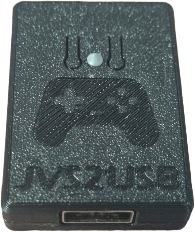 | 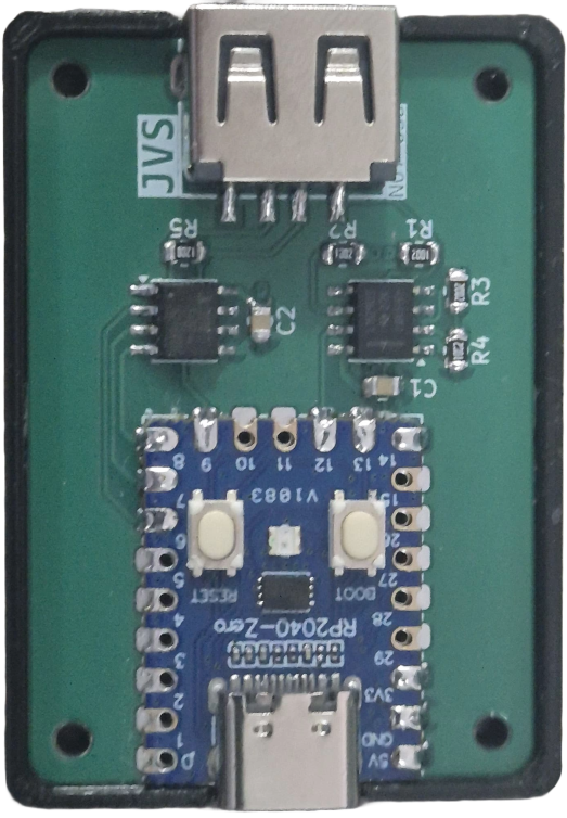 |
To easy assembly, follow this recommended soldering order:
Begin with the surface-mount ICs.
Solder the remaining SMD passives.
Install the USB connector used for the JVS bus physical interface.
Waveshare RP2040-Zero should be installed last
The hw directory includes STL files for a custom 3D-printable enclosure designed specifically for this PCB.
To complete the assembly of the enclosure, you will need the following:
| Qty | Value | Footprint | References |
|---|---|---|---|
| 4 | MountingHole_Pad | MountingHole:MountingHole_2.2mm_M2 | H1, H2, H3, H4 |
| 3 | 10k | Resistor_SMD:R_0805_2012Metric | R1, R2, R4 |
| 2 | 0.1uF | Capacitor_SMD:C_0805_2012Metric | C1, C2 |
| 1 | 120 | Resistor_SMD:R_0805_2012Metric | R5 |
| 1 | 20k | Resistor_SMD:R_0805_2012Metric | R3 |
| 1 | ISL3178EIBZ-T | Package_SO:SOIC-8_3.9x4.9mm_P1.27mm | U2 |
| 1 | LM2903 | Package_SO:SOIC-8_3.9x4.9mm_P1.27mm | U1 |
| 1 | RP2040-Zero | RP2040-Zero-Kicad:RP2040-Zero | RZ1 |
| 1 | USB_A | herzmx:USB-A-TH_C42425 | J1 |
The 15 most common of 16 parts.
It measures 47.6 × 32.8 mm and has 2 copper layers, 1.6 mm thick.
16 parts, built around the ISL3178EIBZ-T, LM2903 and RP2040-ZERO. The full list of its parts is on this page, with links to each part's symbol and footprint where PCBKit's library has them.
From the herzmx/jvs2usb repository on GitHub, at the commit this page was made from: the board is src/jvs2usb.kicad_pcb and its schematic src/jvs2usb.kicad_sch. PCBKit opens the board in the browser, with nothing to install.
Its repository states no licence, so its author keeps all rights: ask herzmx before reusing the design.


max-verem/stm32_ltc_encoder
STM32 based SMPTE Linear Timecode Generator/Reader, isolated input/output

Ansel84/BMW-E30-Gauge-Cluster-Early-Model
This project is the documentation of reverse engineering the BMW E30 gauge cluster for pre 1988 model years.