
2 layers96.5 × 62 mm

Formula Student -- Brake System Plausibility Device
BSPD is an open-source printed circuit board by SDU-Vikings, from the SDU-Vikings/BSPD repository on GitHub, published under the CC0-1.0 licence. It is a 2-layer board of 100 × 50 mm with 110 parts on 72 nets, routed with 452 tracks and 20 vias.
It is built around the CD4041UBE, TEN 8-1223 and TL072, with the CD4043BE, HEF4071BT and LM2903 among its other parts. Its parts include 46 resistors, 11 ICs, 9 diodes, 7 capacitors and 6 transistors.


Formula Student -- Brake System Plausibility Device
Formula Student
Ruleset: FS-Rules_2018_V1.1
This BSPD passed scrutineering at Formula Student UK 2018
Please let us know if you used this design for your car or if you have used it and made useful improvements to it
Also if you have any questions please let us know --> SDU-Vikings
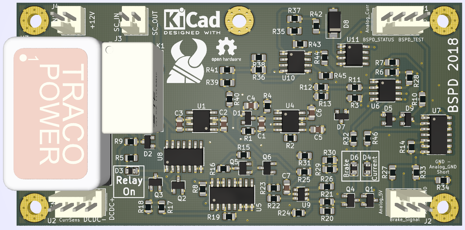
The project is made in KiCad. Get it here --> KiCad 5.0
The schematic layout and PCB layout is found in the KiCad/ subfolder.
The design is made for a battery supply of between 11 V and 15 V.
The current consumption is measured at between 63,0 and 90,3 mA with a 12,7 V supply.
For current measurement LEM HAS 100-S is used. The Hall Effect Sensor needs +-15 V supply hence the TEN 8-1223.
For brake presssure measurement EPT3100 is used.
The relay for the safety chain is TE-OJ-SS-112LMH2.
The design includes SMD-sized LED's for easier debugging. D3 and D4 can be removed altogether and D6 replaced by an ordinary P/N-diode.
LTC6994 is as delay-block. The delay-block is configured for a delay of 500 ms. See LTC6994 One Shot to configure delay and use LTC6994.json for the setup.
The signal from the delay-block is received by a latch CD4043B that will latch on to the signal requiring power cycling of the low voltage system to reset it again.
However the latch will latch on to a high signal when the low voltage system is turned on initially. The 555-circuit is used for generating a pulse, that will reset the latch. The pulse has a delay of approximately 500 ms at turn on.
HAS_100-S has a output voltage range of -12V to +12V with a voltage signal of 4 V for every 100 A in the wire.
With a nominal battery voltage of 510,6 V the current to the motors at 9,8 A is below 5 kW as required by EV7.5.5 in the rules.
510,6 \,\mathrm{V} \cdot 9,7 \,\mathrm{A} \approx 4.953 \,\mathrm{W} At this current in the HV-wires the voltage output from the hall effect sensor is 0,388 V.
The voltage divider between R6 and R11+R12||R13 gives a voltage treshold of 0,380, which corresponds to a current of 9,5 A in the wires.
\frac{2600}{100000 + 2600} \cdot 15\, \mathrm{V} \approx 0,380\, \mathrm{V}Change the value of R6, R11, R12 and R13 to adjust the voltage treshold of the comparator.
Change the value of R27 and R33 to adjust the voltage treshold of the comparator for the brake pressure sensor.
The design includes operational amplifiers whose purpose is to convert the voltage range of the hall effect sensor signal from (-12V/+12V) to (0V/10V) for interfacing with a controller.
It is not required for the intended functionality of the BSPD and can be removed.
U10B is a summation operational amplifier. The gain on the current sensor output is -5/24. This is summed to a voltage of -2,5 V converting the voltage range to (-5 V/0V). U10A has a gain of -2 converting the voltage range to the desired (0V/10V). U11A is a buffer.
DCDC+ +15 V
DCDC- -15 V
BSPD_TEST - Signal from controller to simulate 5 kW drawn from the battery pack
BSPD_STATUS - Signal to controller to show BSPD status. High when there is a BSPD fault
SC_IN - Safety chain in
SC_OUT - Safety chain out
Latch_Reset - From 555-timer-circuit. Used to pulse reset the latch
Current_Sensor - Voltage signal from LEM HAS 100-S
Brake_Sensor - Voltage signal from EPT3100
Analog_GND - Supplied GND to EPT3100. This is shorted to GND at the controller
Analog_5V - 5 V supplied to EPT3100
| Qty | Value | Footprint | References |
|---|---|---|---|
| 12 | 10k | Resistor_SMD:R_0805_2012Metric_Pad1.15x1.40mm_HandSolder | R7, R8, R10, R27, R28, R32, R33, R36, R38, R42, R43, R46 |
| 11 | 10k | Resistor_SMD:R_0805_2012Metric | R1, R2, R4, R5, R9, R14, R15, R16, R18, R19, R23 |
| 5 | BAS16LT1 | Diode_SMD:D_SOT-23_ANK | D1, D2, D5, D7, D9 |
| 4 | 2N7002 | Package_TO_SOT_SMD:TSOT-23 | Q2, Q3, Q5, Q6 |
| 3 | 2,2k | Resistor_SMD:R_0805_2012Metric_Pad1.15x1.40mm_HandSolder | R11, R13, R41 |
| 3 | 22k | Resistor_SMD:R_0805_2012Metric_Pad1.15x1.40mm_HandSolder | R37, R39, R40 |
| 3 | LED | Diode_SMD:D_0805_2012Metric | D3, D4, D6 |
| 2 | 0,1 µF | Capacitor_SMD:C_0805_2012Metric_Pad1.15x1.40mm_HandSolder | C2, C7 |
| 2 | 100k | Resistor_SMD:R_0805_2012Metric_Pad1.15x1.40mm_HandSolder | R3, R6 |
| 2 | 15k | Resistor_SMD:R_0805_2012Metric_Pad1.15x1.40mm_HandSolder | R44, R45 |
| 2 | 3,3k | Resistor_SMD:R_0805_2012Metric_Pad1.15x1.40mm_HandSolder | R20, R21 |
| 2 | 33 | Resistor_SMD:R_0805_2012Metric | R17, R22 |
| 2 | 4,7µ | Capacitor_SMD:C_0805_2012Metric_Pad1.15x1.40mm_HandSolder | C4, C6 |
| 2 | Conn_01x02 | Connector_Molex:Molex_KK-254_AE-6410-02A_1x02_P2.54mm_Vertical | J3, J4 |
| 2 | MMBT3904 | Package_TO_SOT_SMD:TSOT-23 | Q1, Q4 |
| 2 | TL072 | Package_SO:SOIC-8_3.9x4.9mm_P1.27mm | U10, U11 |
| 1 | 0 | Resistor_SMD:R_0805_2012Metric_Pad1.15x1.40mm_HandSolder | R34 |
| 1 | 0,33 µF | Capacitor_SMD:C_0805_2012Metric_Pad1.15x1.40mm_HandSolder | C3 |
| 1 | 100n | Capacitor_SMD:C_0805_2012Metric_Pad1.15x1.40mm_HandSolder | C5 |
| 1 | 10V | Diode_SMD:D_SMA | D8 |
| 1 | 150k | Resistor_SMD:R_0805_2012Metric_Pad1.15x1.40mm_HandSolder | R30 |
| 1 | 1M | Resistor_SMD:R_0805_2012Metric_Pad1.15x1.40mm_HandSolder | R25 |
| 1 | 1µ | Capacitor_SMD:C_0805_2012Metric_Pad1.15x1.40mm_HandSolder | C1 |
| 1 | 220 | Resistor_SMD:R_0805_2012Metric_Pad1.15x1.40mm_HandSolder | R12 |
| 1 | 220k | Resistor_SMD:R_0805_2012Metric_Pad1.15x1.40mm_HandSolder | R35 |
| 1 | 33k | Resistor_SMD:R_0805_2012Metric_Pad1.15x1.40mm_HandSolder | R29 |
| 1 | 680 | Resistor_SMD:R_0805_2012Metric | R24 |
| 1 | 680k | Resistor_SMD:R_0805_2012Metric_Pad1.15x1.40mm_HandSolder | R31 |
| 1 | 68k | Resistor_SMD:R_0805_2012Metric_Pad1.15x1.40mm_HandSolder | R26 |
| 1 | CD4041UB | Package_SO:SOIC-14_3.9x8.7mm_P1.27mm | U8 |
| 1 | CD4043B | Package_SO:SOIC-16_3.9x9.9mm_P1.27mm | U5 |
| 1 | Conn_01x03 | Connector_Molex:Molex_KK-254_AE-6410-03A_1x03_P2.54mm_Vertical | J2 |
| 1 | Conn_01x04 | Connector_Molex:Molex_KK-254_AE-6410-04A_1x04_P2.54mm_Vertical | J1 |
| 1 | HAS_100-S | Connector_Molex:Molex_KK-254_AE-6410-04A_1x04_P2.54mm_Vertical | U2 |
| 1 | HEF4071 | Package_SO:SOIC-14_3.9x8.7mm_P1.27mm | U7 |
| 1 | L78L05_SO8 | Package_SO:SOIC-8_3.9x4.9mm_P1.27mm | U1 |
| 1 | LM2903 | Package_SO:SOIC-8_3.9x4.9mm_P1.27mm | U6 |
| 1 | LM555 | Package_SO:SOIC-8_3.9x4.9mm_P1.27mm | U4 |
| 1 | LOGO | Vikings_Graphics:VikingLogo_Silk_9x10mm | G*** |
| 1 | LTC6994 | Package_TO_SOT_SMD:SOT-23-6 | U9 |
| 1 | TE-OJ-SS-112LMH2 | Vikings_devices:TE-OJ-Series_Miniature-PCB-Relay | K1 |
| 1 | TEN8-1223 | Vikings_devices:TEN8-1223 | U3 |
The 85 most common of 110 parts.
It measures 100 × 50 mm and has 2 copper layers, 1.6 mm thick.
110 parts, built around the CD4041UBE, TEN 8-1223, TL072 and CD4043BE. The full list of its parts is on this page, with links to each part's symbol and footprint where PCBKit's library has them.
From the SDU-Vikings/BSPD repository on GitHub, at the commit this page was made from: the board is KiCad/BSPD.kicad_pcb. PCBKit opens the board in the browser, with nothing to install.
Its repository publishes it under the CC0-1.0 licence: you may reuse it on that licence's terms (keep the author's notice, and for a copyleft licence share your changes alike).

UAA-F14/PCBs-Design
Power electronics PCB coursework — SCR controller, buck converter, Class D amplifier, DC-AC inverter, and a protected power supply Resources

IKGB105/PCBs-POWER-ELECTRONICS
Power electronics PCB coursework — SCR controller, buck converter, Class D amplifier, DC-AC inverter, and a protected power supply Resources

ManchesterStingerMotorsports/IMD_Carrier
Reset board for the imd that will sit below it in the TSAC

ttoomat/KiCad_MOSFET_Drv
My schematics and PCBs for MOSFET + driver -> AC switches -> Half-bridges -> motor control.


trublion/Boite_a_bourdon_control_board
HW control board for motorised hurgy-gurdy. Controls a DC motor with a half-H-bridge, reads an analog audio signal envelope, dual-PCB design.

yminp/dj-filter-fx
A voltage-controlled DJ filter unit with LFO-like envelope function