4 layers152.5 × 161.6 mm
MB PCB ControladorESP32
Miguel-Barcelos/Electronics-Projects
Este repositório contém projetos de eletrônica, incluindo circuitos eletrônicos, simulações e design de PCBs.
203 parts

 hasan-abuzaid/nft-hydroponic-controller
Open-hardware ESP32-S3 controller for NFT hydroponics: pH/EC/level sensing, 6 relay channels, ESPHome + Home Assistant
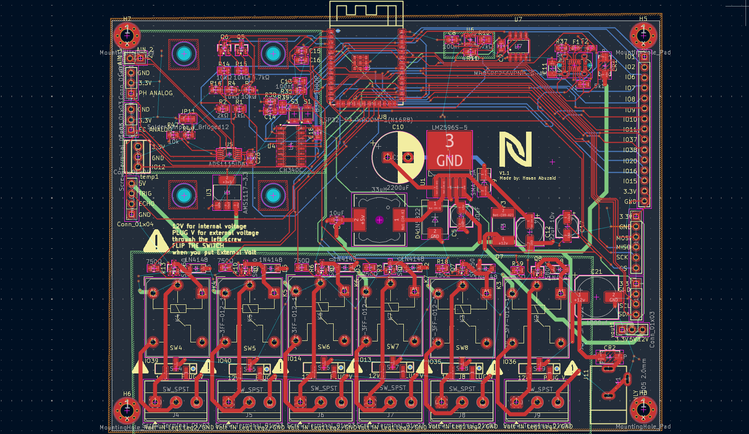
Nft hydroponic controller is an open-source printed circuit board by hasan-abuzaid, from the hasan-abuzaid/nft-hydroponic-controller repository on GitHub, published under the CERN-OHL-S-2.0 licence. It is a 4-layer board of 135 × 101.3 mm with 107 parts on 138 nets, routed with 1,166 tracks and 207 vias.
It is built around the CH340C, ADS1115IDGS and BME280, with the LM2596S-5.0, AMS1117-3.3 and MB85RC256VPNF-G-AMERE2 among its other parts. Its parts include 22 resistors, 15 capacitors, 14 switches, 12 connectors and 8 diodes. It belongs with the home automation and IoT boards and the ESP32 boards of this library.


Status: v1.1 boards fabricated and assembled by JLCPCB. Bring-up and on-site testing in progress.
A 4-layer, ESP32-S3 based controller board that turns a manual NFT (Nutrient Film Technique) hydroponic system into a self-regulating one. It reads pH, EC and water level from the main reservoir, switches up to six 12 V pumps (nutrient A, nutrient B, pH adjust, circulation, …) and integrates natively with Home Assistant through ESPHome.
The goal: replace the breadboards, loose jumper wires and relay modules that most DIY hydroponic builds end up with, with one board you can order pre-assembled from JLCPCB, screw your sensors and pumps into, and flash.
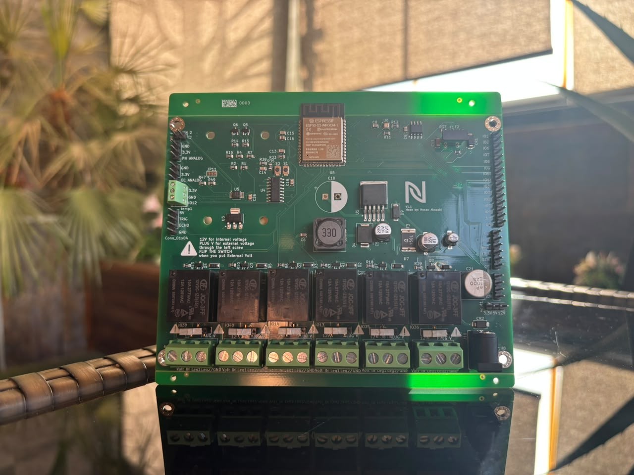
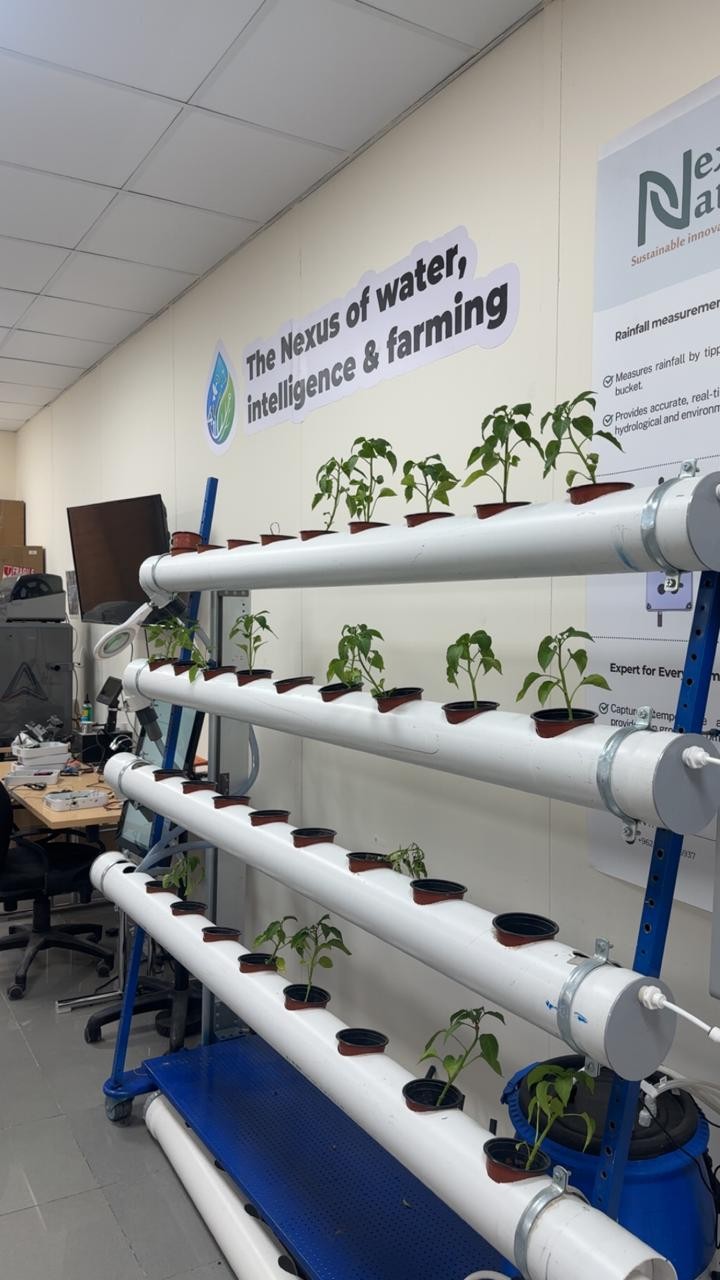
NFT systems work by running a thin film of nutrient solution under the plant roots. The hard part is not the plumbing, it is keeping the solution chemistry right: pH drifts, EC drops as plants feed, and the tank level falls. Doing that by hand every day is what makes most home systems fail.
This board closes that loop:
 pH / EC / level sensors ──► ESP32-S3 ──► Home Assistant (automations decide dose)
          ▲                                      │
          └──── main tank ◄── dosing pumps ◄── relays ◄─┘
The ESP reports readings, Home Assistant decides how much A/B nutrient or pH-down to dose based on calibrated set-points, and the board drives the pumps.
| Block | Implementation |
|---|---|
| MCU | ESP32-S3-WROOM-1 (N16R8) — 16 MB flash, 8 MB PSRAM, Wi-Fi + BLE |
| USB | USB-C, CH340C USB-UART bridge with auto-reset/auto-boot (flash with no button presses), ESD protection on the data lines |
| Power input | 12 V DC barrel jack (DC-005, 2.0 mm) |
| Power conversion | LM2596S-5 buck (12 V → 5 V), AMS1117-3.3 LDO (5 V → 3.3 V) |
| Protection | SMAJ15A TVS on the 12 V rail, resettable polyfuse, Schottky OR-ing between USB and 12 V supply |
| Analog front-end | ADS1115 16-bit ADC for the pH and EC probe signals (far more stable than the ESP32's internal ADC) |
| Sensor inputs | pH and EC analog headers, water-temperature screw terminal, ultrasonic level header (5 V / TRIG / ECHO / GND), I²C header, GPIO breakout |
| Environment | On-board BME280 (air temperature, humidity, pressure) |
| Storage | MB85RC256V 32 KB I²C FRAM — stores calibration and state without flash wear |
| Outputs | 6× relay channels (JQC-3FF, SPDT) on 3-pin screw terminals (Volt IN / Leg 1 / Leg 2-GND), each with flyback diode and transistor driver |
| Load supply select | Per-channel switch: power the load from the board's internal 12 V, or from an external supply wired into that channel's Volt IN terminal |
| Buttons | BOOT and RESET |
| Power outputs | 3.3 V / 5 V / 12 V header for external modules |
| PCB | 4-layer, 1.6 mm, JLCPCB-ready (LCSC part numbers in the BOM) |
.
├── nft-hydroponic-controller.kicad_pro   KiCad project (open this)
├── nft-hydroponic-controller.kicad_sch   Schematic
├── nft-hydroponic-controller.kicad_pcb   PCB layout
├── nft-hydroponic-controller.kicad_dru   Custom design rules
├── nft-hydroponic-controller.csv         Bill of materials with LCSC part numbers
├── nft-hydroponic-controller.xml         Netlist
├── DRC.rpt, ERC.rpt                      Design rule / electrical rule check reports
├── libs/lcsc/                Symbols, footprints and 3D models imported from LCSC
├── Custom_JLCPCB_Parts/      Custom parts library
├── compunents/               Additional vendor symbols/footprints
├── fp-lib-table, sym-lib-table   Project-relative library tables
├── firmware/esphome/         ESPHome config + secrets template
└── docs/images/              Photos and renders
All library paths are project-relative, so the project opens without missing symbols or footprints on a fresh machine.
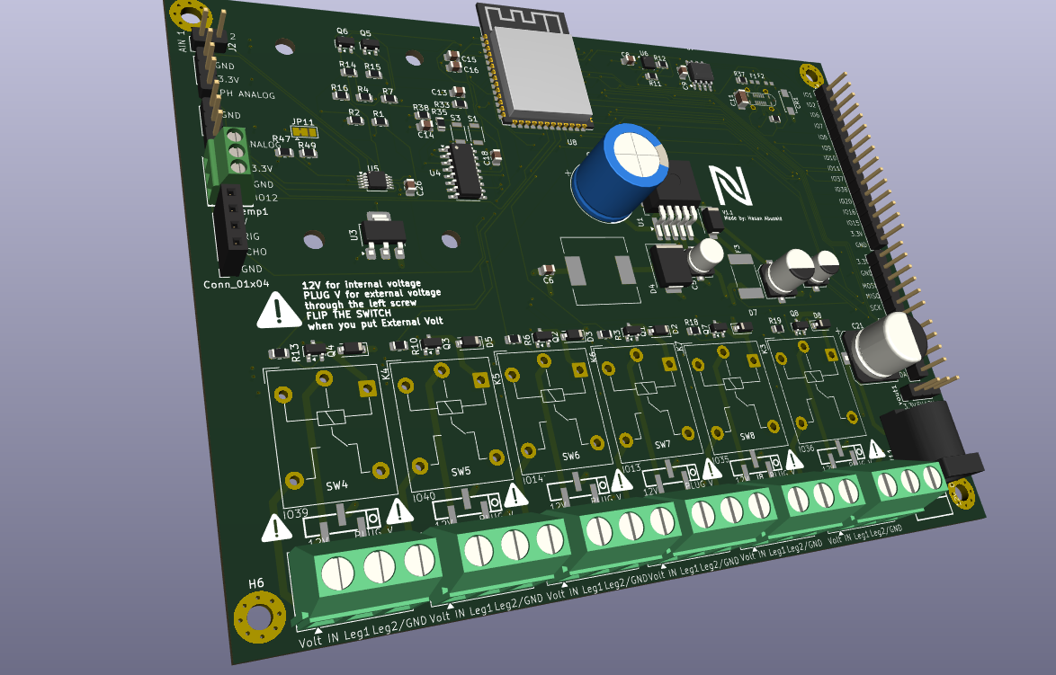
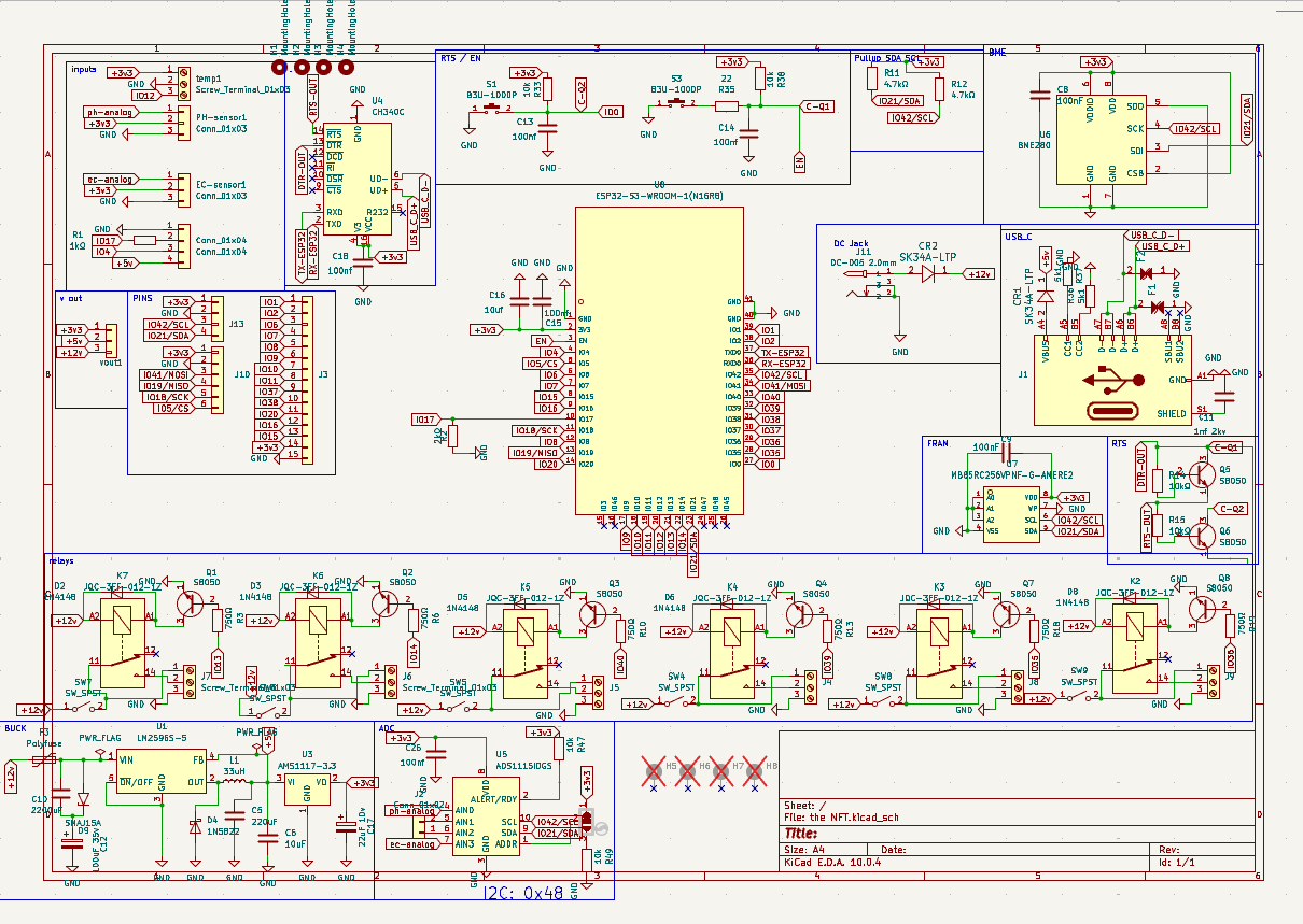
fabrication-toolkit-options.jsonnft-hydroponic-controller.kicad_pro in KiCad.Ready-made manufacturing files are also attached to each Release.
Each channel's terminal block is Volt IN / Leg 1 / Leg 2-GND.
| Function | ESP32-S3 GPIO |
|---|---|
| Relay 1 | GPIO39 |
| Relay 2 | GPIO40 |
| Relay 3 | GPIO14 |
| Relay 4 | GPIO13 |
| Relay 5 | GPIO35 |
| Relay 6 | GPIO36 |
| I²C SDA (ADS1115, BME280, FRAM) | GPIO21 |
| I²C SCL | GPIO42 |
| Water temperature | GPIO12 |
| Ultrasonic level (trig / echo) | GPIO4 / GPIO17 (echo through a 1k/2k divider, 5 V-safe) |
ADS1115 (I²C address 0x48): pH → AIN0, EC → AIN3.
The board runs ESPHome and reports to Home Assistant over MQTT (with MQTT discovery, so entities appear automatically). The config is in firmware/esphome/nutrient-controller.yaml.
This is the configuration used during development. Check the pin assignments against the pin mapping above before flashing it to the v1.1 board.
Setup:
firmware/esphome/secrets.yaml.example to secrets.yaml and fill in your Wi-Fi, MQTT broker and passwords.pH and EC probes drift and vary between units, so set-points must be calibrated per probe:
| Revision | v1.1 |
| Boards | Fabricated and assembled (JLCPCB) |
| Tested | Not yet — bring-up results will be posted here |
| Known issues | Relays 5 and 6 use GPIO35/36. On the N16R8 module these pins are wired to the octal PSRAM. Leave PSRAM disabled in firmware and verify both channels during bring-up; fix planned for the next revision. |
Issues and pull requests are welcome, especially: tested pin mappings for other sensor probes, enclosure designs, and Home Assistant automation improvements. If you build one, open an issue with a photo.
Designed by Hasan Abuzaid — Mechatronics Engineering, German Jordanian University. Developed during an IoT/embedded internship at Nexus Nature.
Hardware: CERN-OHL-S-2.0. Firmware and configuration files: MIT.
| Qty | Value | Footprint | References |
|---|---|---|---|
| 8 | S8050 | Package_TO_SOT_SMD:SOT-23 | Q1, Q2, Q3, Q4, Q5, Q6, Q7, Q8 |
| 6 | 1N4148 | Diode_SMD:D_SOD-123 | D2, D3, D5, D6, D7, D8 |
| 6 | 750Ω | Resistor_SMD:R_0805_2012Metric | R3, R6, R10, R13, R18, R19 |
| 6 | JQC-3FF-012-1Z | Relay_THT:Relay_SPDT_Hongfa_JQC-3FF_0XX-1Z | K2, K3, K4, K5, K6, K7 |
| 6 | SW_SPST | lcsc_footprints:C515802_SW-SMD_NSI-10S | SW4, SW5, SW6, SW7, SW8, SW9 |
| 6 | Screw_Terminal_01x03 | TerminalBlock_Phoenix:TerminalBlock_Phoenix_MKDS-1,5-3-5.08_1x03_P5.08mm_Horizontal | J4, J5, J6, J7, J8, J9 |
| 5 | 100nf | Capacitor_SMD:C_0805_2012Metric | C13, C14, C15, C18, C26 |
| 4 | 10k | Resistor_SMD:R_0805_2012Metric | R33, R38, R47, R49 |
| 4 | 10kΩ | Resistor_SMD:R_0805_2012Metric | R4, R7, R14, R15 |
| 4 | MountingHole | MountingHole:MountingHole_3.2mm_M3_ISO7380 | H1, H2, H3, H4 |
| 4 | MountingHole_Pad | MountingHole:MountingHole_3.2mm_M3_Pad_Via | H5, H6, H7, H8 |
| 3 | 4.7kΩ | Resistor_SMD:R_0805_2012Metric | R11, R12, R16 |
| 3 | Conn_01x03 | Connector_PinHeader_2.54mm:PinHeader_1x03_P2.54mm_Vertical | EC-sensor1, PH-sensor1, vout1 |
| 2 | 100nF | Capacitor_SMD:C_0805_2012Metric | C8, C9 |
| 2 | 5k1 | Resistor_SMD:R_0805_2012Metric | R36, R37 |
| 2 | B3U-1000P | B3U-1000P:SW_B3U-1000P | S1, S3 |
| 2 | PGB1010603MRHF | PGB1010603:FUSE_PGB10106_LTF | F1, F2 |
| 2 | SK34A-LTP | SK34A-LTP:SMADO-214AC_MCC | CR1, CR2 |
| 1 | 1000uf | Capacitor_SMD:CP_Elec_10x10.5 | C21 |
| 1 | 100uF 35v | Capacitor_SMD:CP_Elec_6.3x7.7 | C12 |
| 1 | 10uF | Capacitor_SMD:C_0805_2012Metric | C6 |
| 1 | 10uf | Capacitor_SMD:C_0805_2012Metric | C16 |
| 1 | 1N5822 | Diode_SMD:D_SMC | D4 |
| 1 | 1kΩ | Resistor_SMD:R_0805_2012Metric | R1 |
| 1 | 1nf 2kv | Capacitor_SMD:C_1206_3216Metric | C11 |
| 1 | 22 | Resistor_SMD:R_0805_2012Metric | R35 |
| 1 | 2200uF | Capacitor_THT:CP_Radial_D12.5mm_P5.00mm | C10 |
| 1 | 220uF | Capacitor_SMD:C_Elec_5x5.4 | C5 |
| 1 | 22uF 10v | Capacitor_SMD:CP_Elec_5x5.4 | C17 |
| 1 | 2kΩ | Resistor_SMD:R_0805_2012Metric | R2 |
| 1 | 33uH | Inductor_SMD:L_12x12mm_H6mm | L1 |
| 1 | ADS1115IDGS | Package_SO:TSSOP-10_3x3mm_P0.5mm | U5 |
| 1 | AMS1117-3.3 | Package_TO_SOT_SMD:SOT-223-3_TabPin2 | U3 |
| 1 | BME280 | Package_LGA:Bosch_LGA-8_2.5x2.5mm_P0.65mm_ClockwisePinNumbering | U6 |
| 1 | CH340C | Package_SO:SOIC-16_3.9x9.9mm_P1.27mm | U4 |
| 1 | Conn_01x02 | Connector_PinHeader_2.54mm:PinHeader_1x02_P2.54mm_Vertical | J2 |
| 1 | Conn_01x04 | Connector_PinSocket_2.54mm:PinSocket_1x04_P2.54mm_Vertical | Conn_01x04 |
| 1 | Conn_01x04 | Connector_PinHeader_2.54mm:PinHeader_1x04_P2.54mm_Vertical | J13 |
| 1 | Conn_01x06 | Connector_PinHeader_2.54mm:PinHeader_1x06_P2.54mm_Vertical | J10 |
| 1 | Conn_01x15 | Connector_PinHeader_2.54mm:PinHeader_1x15_P2.54mm_Vertical | J3 |
| 1 | DC-005 2.0mm | lcsc_footprints:C84007_DC-IN-TH_DC-005C-20A | J11 |
| 1 | ESP32-S3-WROOM-1(N16R8) | lcsc_footprints:C2913202_WIRELM-SMD_ESP32-S3-WROOM-1 | U8 |
| 1 | LM2596S-5 | Package_TO_SOT_SMD:TO-263-5_TabPin3 | U1 |
| 1 | LOGO | LOGO | G*** |
| 1 | MB85RC256VPNF-G-AMERE2 | lcsc_footprints:C45273903_SOP-8_L4_9-W3_9-P1_27-LS6_0-BL | U7 |
| 1 | Polyfuse | Fuse:Fuse_2920_7451Metric_Pad2.10x5.45mm_HandSolder | F3 |
| 1 | SMAJ15A | Diode_SMD:D_SMA | D9 |
| 1 | Screw_Terminal_01x03 | lcsc_footprints:C474921_CONN-TH_3P-P2_54_KF128-2_54-3P | temp1 |
| 1 | SolderJumper_3_Bridged12 | Jumper:SolderJumper-3_P1.3mm_Bridged12_Pad1.0x1.5mm | JP11 |
| 1 | USB_C_Receptacle_USB2.0_16P | USB_TYPE_C_standing:USB_C_Standing | J1 |
Miguel-Barcelos/Electronics-Projects
Este repositório contém projetos de eletrônica, incluindo circuitos eletrônicos, simulações e design de PCBs.


schoolllex/ESPBoosted
A custom, feature-rich ESP32-WROOM-32 development board featuring built-in environmental sensors, power management, and expansion interfaces.

hatlabs/HALMET-hardware
Hat Labs Marine Engine & Tank interface hardware design files


beaked99/air-scales
2025-11-20. Updated all the footprints and symbols to their proper layouts. no more fkn errors. Hallefuckinglujah. Fucked up with LM74610 not using the right footprint. minor fix. 2025-11-16.

It measures 135 × 101.3 mm and has 4 copper layers, 1.6 mm thick.
107 parts, built around the CH340C, ADS1115IDGS, BME280 and LM2596S-5.0. The full list of its parts is on this page, with links to each part's symbol and footprint where PCBKit's library has them.
From the hasan-abuzaid/nft-hydroponic-controller repository on GitHub, at the commit this page was made from: the board is nft-hydroponic-controller.kicad_pcb and its schematic nft-hydroponic-controller.kicad_sch. PCBKit opens the board in the browser, with nothing to install.
Its repository publishes it under the CERN-OHL-S-2.0 licence: you may reuse it on that licence's terms (keep the author's notice, and for a copyleft licence share your changes alike).