Skip to the content
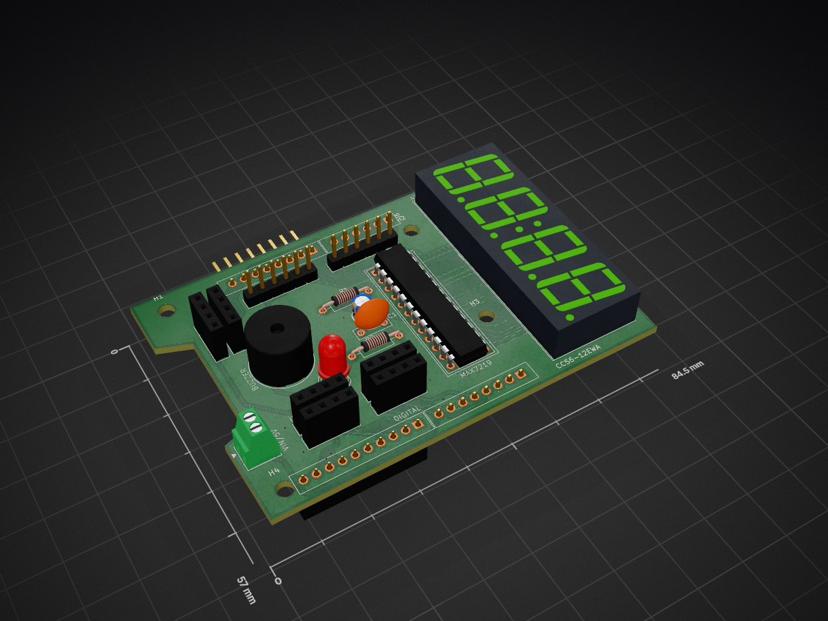
2 layers84.5 × 57 mmArduino uno v1.2, the printed circuit board in 3D

Arduino Uno R3 Multifunction Shield | KiCad PCB Design | Two-Layer PCB | Open Source Hardware

Size
84.5 × 57 mm
Copper layers
2
Thickness
1.6 mm
Parts
25
Nets
48
Pads
124
Tracks, vias
302, 17
Pours
1
Routed
Yes
KiCad
KiCad 9.0 (file 20241229)
Created
8 Jul 2026
Updated
8 Jul 2026

Overview

Arduino uno v1.2 is an open-source printed circuit board by hardikshrimali-ece, from the hardikshrimali-ece/CUSTOM-ARDUINO-UNO-R3-SHIELD..- repository on GitHub. It is a 2-layer board of 84.5 × 57 mm with 25 parts on 48 nets, routed with 302 tracks and 17 vias.

It is built around the MAX7219M and CC56-12EWA. Its parts include 6 connectors, 2 capacitors, 2 resistors, 1 IC and 1 diode.

Main components

2

README

README.md

CUSTOM-ARDUINO-UNO-R3-SHILED-

Arduino Uno R3 Multifunction Shield | KiCad PCB Design | Two-Layer PCB | Open Source Hardware Arduino Uno R3 Multifunction Shield

A custom Arduino Uno R3 compatible multifunction shield designed using KiCad as part of my PCB Design and Embedded Systems learning journey.

This project focuses on understanding the complete hardware development workflow from schematic creation to PCB layout and manufacturing-ready design.

Project Objective

The purpose of this project is to gain practical experience in professional PCB Design by designing a multifunction Arduino Uno Shield instead of simply assembling existing hardware.

The design emphasizes:

  • Clean PCB Layout
  • Practical Routing
  • Commercial Style Component Placement
  • Design Verification
  • Manufacturing Ready Files

Features

  • Arduino Uno R3 Compatible
  • MAX7219 4-Digit Seven Segment Display
  • Buzzer
  • Status LEDs
  • Expansion Headers
  • Two Layer PCB
  • Ground Plane (Copper Pour)
  • 3D PCB Model

Design Workflow

  • Requirement Planning
  • Schematic Design
  • Component Selection
  • Footprint Assignment
  • PCB Component Placement
  • Two Layer Routing
  • Via Optimization
  • Copper Pour
  • DRC Verification
  • 3D Inspection
  • Gerber Generation

Skills Learned

This project helped me gain practical experience in:

  • KiCad Schematic Editor
  • PCB Layout Design
  • Component Placement
  • Footprint Selection
  • Two Layer Routing
  • Copper Pour
  • Via Usage
  • Design Rule Check (DRC)
  • PCB Design Review
  • 3D PCB Verification
  • Gerber Generation

Current Status

  • ✅ Schematic Completed
  • ✅ PCB Layout Completed
  • ✅ Two Layer Routing Completed
  • ✅ 3D Model Verified
  • ✅ Gerber Files Generated

Physical Manufacturing

The current version is a manufacturing-ready PCB design.

The board has not been fabricated because the primary objective of this revision was to learn professional PCB Design methodology. Fabrication may be considered in future revisions when required.

Future Improvements (Revision 2)

  • Push Buttons
  • OLED Header
  • Arduino Uno R4 Compatibility
  • SMD Optimized Version
  • Additional Expansion Features

Future Projects

  • Arduino Drone Expansion Shield
  • Arduino Uno Original PCB
  • ESP32 Development Board
  • STM32 Flight Controller
  • UAV Electronics

Tools Used

  • KiCad

License

Open-source project created for learning, education, and hardware design practice.

Author

Hardik Shrimali K

B.Tech Electronics and Communication Engineering (ECE) (1st year)

Interested in:

  • Embedded Systems
  • PCB Design
  • UAV Electronics
  • Robotics
  • Defense Technology

Parts

25
QtyValueFootprintReferences
6I2CConnector_PinHeader_2.54mm:PinHeader_1x04_P2.54mm_VerticalI2C1, I2C2, PWR, PWR2, UART, UART1
4MountingHoleMountingHole:MountingHole_3.2mm_M3H1, H2, H3, H4
10.1mFCapacitor_THT:C_Disc_D7.0mm_W2.5mm_P5.00mmC1
11.2kResistor_THT:R_Axial_DIN0207_L6.3mm_D2.5mm_P10.16mm_HorizontalR2
110kResistor_THT:R_Axial_DIN0207_L6.3mm_D2.5mm_P10.16mm_HorizontalR1
110mFCapacitor_THT:CP_Radial_D4.0mm_P2.00mmC2
1ANALOGConnector_PinHeader_2.54mm:PinHeader_1x06_P2.54mm_VerticalJ2
1BuzzerBuzzer_Beeper:MagneticBuzzer_ProSignal_ABI-010-RCBZ1
1CC56-12EWADisplay_7Segment:CA56-12EWA4D7SD1
1LEDLED_THT:LED_D5.0mmD1
1MAX7219Package_DIP:DIP-24_W7.62mm_SocketU1
1PWMConnector_PinHeader_2.54mm:PinHeader_1x06_P2.54mm_VerticalSPIN1
1VIN 5VTerminalBlock_Phoenix:TerminalBlock_Phoenix_MPT-0,5-2-2.54_1x02_P2.54mm_HorizontalJ1
1analog02Connector_PinHeader_2.54mm:PinHeader_1x06_P2.54mm_VerticalJ6
1analog1Connector_PinHeader_2.54mm:PinHeader_1x08_P2.54mm_VerticalJ5
1digital01Connector_PinHeader_2.54mm:PinHeader_1x10_P2.54mm_VerticalJ3
1digital02Connector_PinHeader_2.54mm:PinHeader_1x08_P2.54mm_VerticalJ4

Similar boards

  • 2 layers80 × 68.8 mmARDUINO UNO SHIELD V3.0, the printed circuit board in 3D

    ARDUINO UNO SHIELD V3.0

    hardikshrimali-ece/-ARDUINO-UNO-R3-SHIELD-V3.0

    Arduino Uno Multifunction Shield V3.0 built in KiCad with integrated 4-digit MAX7219 display, UART, I2C, PWM, power headers, buzzer, LEDs, and push buttons.

    39 parts
  • 2 layersTachmetr V2, the printed circuit board in 3D

    Tachmetr V2

    Wladymyr1996/TachMetr-V2.0

    The is a LED tachometer for my trike. Work on Atmega8A_AU and MAX7219.

    63 parts
  • 2 layers54.6 × 71.8 mmThermostat, the printed circuit board in 3D

    Thermostat

    protaskin/AVRThermostat

    A programmable thermostat on ATmega8A and DS18B20.

    31 parts7MIT
  • 2 layers55 × 84.4 mmOpenReflowPlate, the printed circuit board in 3D

    OpenReflowPlate

    makingdevices/OpenReflowPlate

    An Open Reflow Plate machine for smd soldering

    71 parts6
  • 4 layers65 × 45 mmStopWatch, the printed circuit board in 3D

    StopWatch

    makingdevices/StopWatch

    This project is a simple StopWatch for measuring times on different processes or activities.

    55 parts5GPL-3.0
  • 6 layers210 × 119 mmClaculator Keypad, the printed circuit board in 3D

    Claculator Keypad

    Robert-Mones/Claculator

    A reverse Polish notation calculator with added features such as comparisons, branching, and custom recursive operators taken from the Clac project from the 15-122 course at Carnegie Mellon University.

    202 parts5
  • 2 layers40 × 65 mmBytesCounter, the printed circuit board in 3D

    BytesCounter

    makingdevices/Bytes-Counter

    Bytes Counter is a Open Source Tally Counter HW project

    36 parts4GPL-3.0
  • 2 layers174.5 × 90.4 mmVolante Maquinillo, the printed circuit board in 3D

    Volante Maquinillo

    Angelpele/F1-Steering-Wheel

    F1 Functional Steering Wheel based on the ESP32

    65 parts2

Questions

How big is the Arduino uno v1.2 PCB?

It measures 84.5 × 57 mm and has 2 copper layers, 1.6 mm thick.

What parts does the Arduino uno v1.2 use?

25 parts, built around the MAX7219M and CC56-12EWA. The full list of its parts is on this page, with links to each part's symbol and footprint where PCBKit's library has them.

Where can I download the Arduino uno v1.2 KiCad files?

From the hardikshrimali-ece/CUSTOM-ARDUINO-UNO-R3-SHIELD..- repository on GitHub, at the commit this page was made from: the board is arduino uno v1.2.kicad_pcb and its schematic arduino uno v1.2.kicad_sch. PCBKit opens the board in the browser, with nothing to install.

Can I use the Arduino uno v1.2 design in my own project?

Its repository states no licence, so its author keeps all rights: ask hardikshrimali-ece before reusing the design.