

2 layers54.6 × 71.8 mm

 Angelpele/F1-Steering-Wheel2
F1 Functional Steering Wheel based on the ESP32
Volante Maquinillo is an open-source printed circuit board by Angelpele, from the Angelpele/F1-Steering-Wheel repository on GitHub. It is a 2-layer board of 174.5 × 90.4 mm with 65 parts on 68 nets, routed with 502 tracks and 172 vias.
It is built around the ESP32-C6-DEVKITC-1-N8 and CC56-12EWA. Its parts include 26 resistors, 15 diodes, 8 switches, 3 ICs and 2 connectors. It belongs with the ESP32 and RISC-V boards of this library.
This project is a custom-made F1-style steering wheel designed and built entirely from scratch, featuring a custom PCB, advanced input/output handling, and a rigid mechanical structure optimized for sim racing or small racing karts.
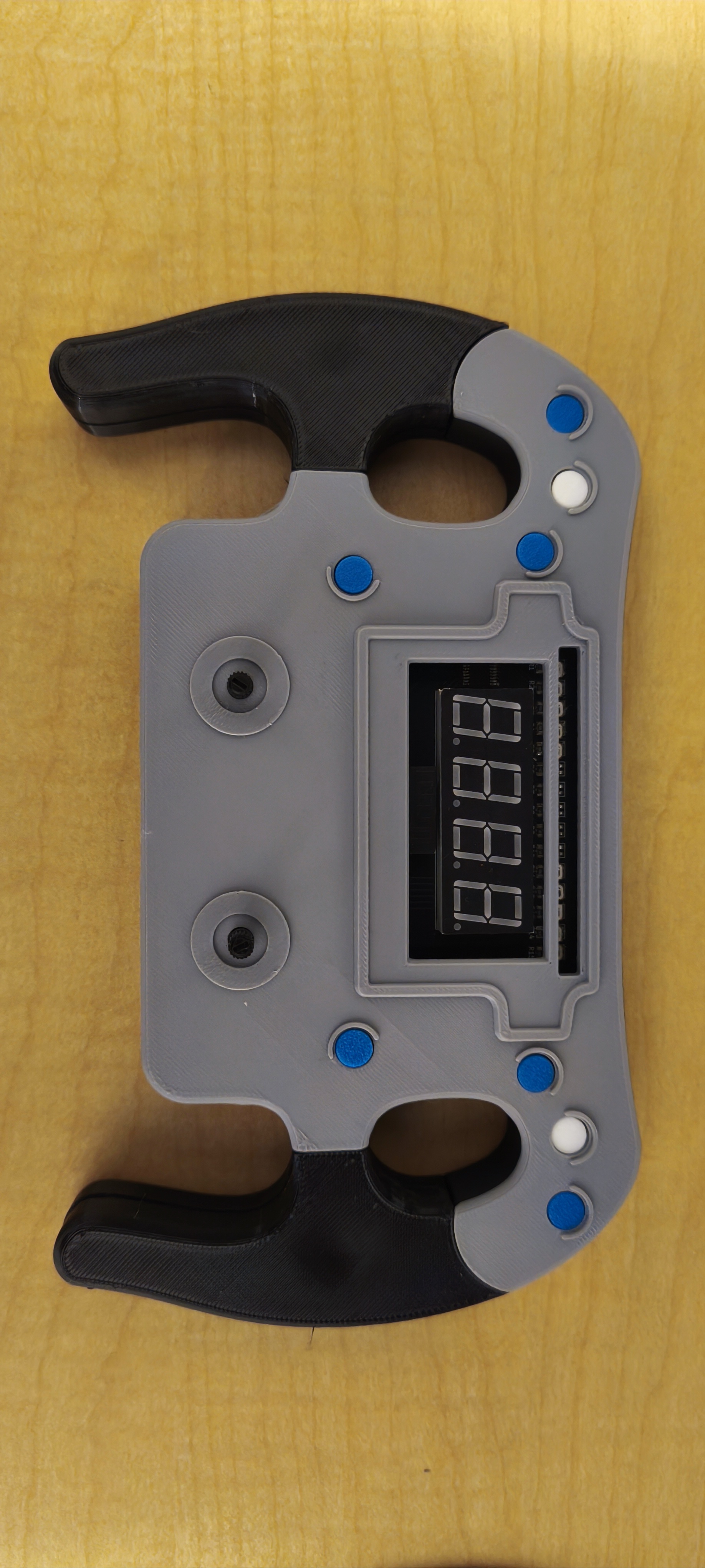
The steering wheel is built around a custom-designed PCB using an ESP32-C6 DevKitC-1 as the main controller, providing high performance and wireless capabilities.
| Component | Description |
|---|---|
| ESP32-C6 DevKitC-1 | Main microcontroller handling inputs, logic, and communication |
| 74LS154 Decoder | 4-to-16 line decoder used to drive LED array |
| 15 LEDs (RGB Groups) | Divided into 3 groups of 5 LEDs (Green, Red, Blue) |
| 4-Digit 7-Segment Display | Displays speed, gear, or system information |
| 8 Buttons (Resistor Ladder) | All buttons read through a single ADC pin |
| 2 Potentiometers | Center mounted, using voltage divider for analog input |
| Buzzer | Return sound feedback to the user reacting to different variables |
| External Sensor Support | Designed for external NTC temperature sensor and Hall-effect sensor inputs |
| Custom Buttons PCB | Top-mounted buttons integrated into the housing |
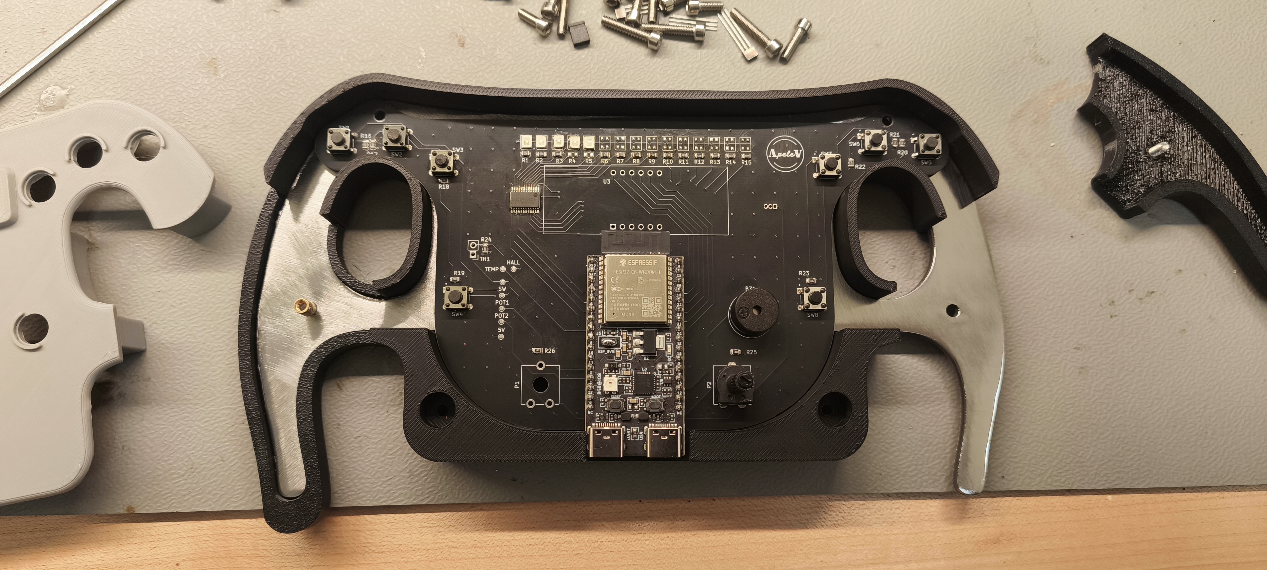
The 15 LEDs, controlled via the 74LS154 decoder, provide real-time visual feedback:
The decoder uses 4 control lines to efficiently manage all LED outputs.
The 8 buttons are arranged with a resistor ladder configuration, reading all the possible values with an ADC converter (analog input).
📄 Find the Circuit Schematic right below:
The entire mechanical structure was designed from scratch in Fusion 360, prioritizing rigidity, modularity, and professional finish.
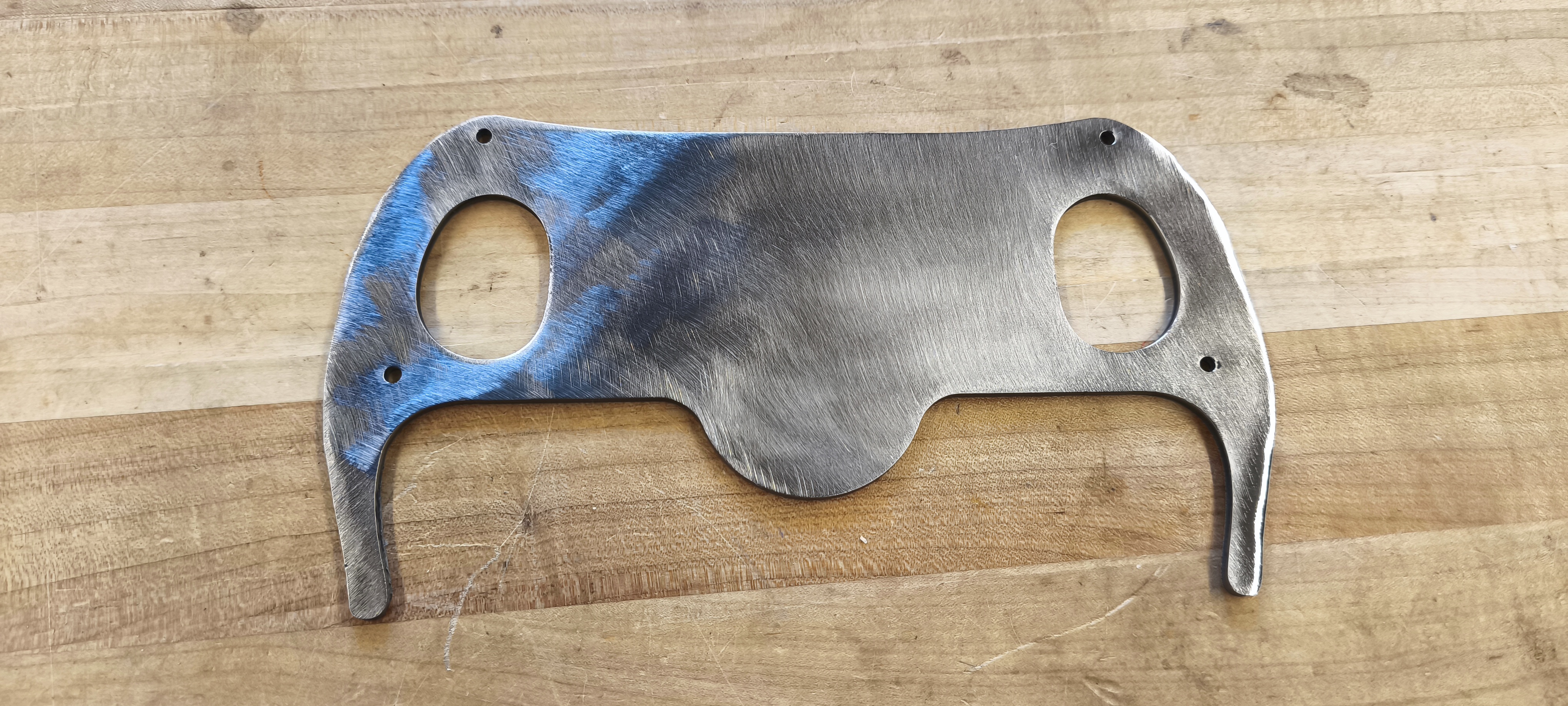
Lower Case
Steel Reinforcement Plate
TPU Handles
PCB Mounting
Top Case & Buttons
| Qty | Value | Footprint | References |
|---|---|---|---|
| 15 | LED | LED_SMD:LED_Cree-PLCC4_3.2x2.8mm_CCW | D1, D2, D3, D4, D5, D6, D7, D8, D9, D10, D11, D12, D13, D14, D15 |
| 11 | 10k | Resistor_SMD:R_0805_2012Metric | R16, R17, R18, R19, R20, R21, R22, R23, R24, R25, R26 |
| 10 | 100 | Resistor_SMD:R_0805_2012Metric | R1, R2, R3, R4, R5, R11, R12, R13, R14, R15 |
| 8 | SW_SPST | Spst_SW:SW_TS02-66-60-BK-100-LCR-D | SW1, SW2, SW3, SW4, SW5, SW6, SW7, SW8 |
| 5 | 150 | Resistor_SMD:R_0805_2012Metric | R6, R7, R8, R9, R10 |
| 2 | R_Variable | Potentiometer_THT:Potentiometer_ACP_CA9-V10_Vertical_Hole | P1, P2 |
| 1 | 0.1 uF | Capacitor_SMD:C_0805_2012Metric | C1 |
| 1 | 3V3 | TestPoint:TestPoint_Pad_D1.0mm | TP2 |
| 1 | 5V | TestPoint:TestPoint_Pad_D1.0mm | TP1 |
| 1 | 74LS154 | Package_SO:TSSOP-24_4.4x7.8mm_P0.65mm | U1 |
| 1 | Buzzer | Buzzer_Beeper:Buzzer_12x9.5RM7.6 | BZ1 |
| 1 | CC56-12EWA | Display_7Segment:CA56-12EWA | U3 |
| 1 | ESP32-C6-DEVKITC-1-N8 | ESP32-C6-DEVKITC-1-N8:MODULE_ESP32-C6-DEVKITC-1-N8 | U2 |
| 1 | HALL | TestPoint:TestPoint_Pad_D1.0mm | TP4 |
| 1 | HALL | Package_TO_SOT_THT:TO-92Flat | Q1 |
| 1 | POT1 | TestPoint:TestPoint_Pad_D1.0mm | TP6 |
| 1 | POT2 | TestPoint:TestPoint_Pad_D1.0mm | TP7 |
| 1 | SW | TestPoint:TestPoint_Pad_D1.0mm | TP5 |
| 1 | TEMP | TestPoint:TestPoint_Pad_D1.0mm | TP3 |
| 1 | Thermistor_NTC | Connector_PinHeader_2.54mm:PinHeader_1x02_P2.54mm_Vertical | TH1 |


makingdevices/StopWatch
This project is a simple StopWatch for measuring times on different processes or activities.

Robert-Mones/Claculator
A reverse Polish notation calculator with added features such as comparisons, branching, and custom recursive operators taken from the Clac project from the 15-122 course at Carnegie Mellon University.

makingdevices/Bytes-Counter
Bytes Counter is a Open Source Tally Counter HW project


xuejun7777/Comprehensive-Design-and-Practice-Project-A---Digital-Thermometer-Based-on-NTC
综合设计与实践A项目-基于NTC的数字温度计

It measures 174.5 × 90.4 mm and has 2 copper layers, 1.6 mm thick.
65 parts, built around the ESP32-C6-DEVKITC-1-N8 and CC56-12EWA. The full list of its parts is on this page, with links to each part's symbol and footprint where PCBKit's library has them.
From the Angelpele/F1-Steering-Wheel repository on GitHub, at the commit this page was made from: the board is Hardware/Volante Maquinillo.kicad_pcb and its schematic Hardware/Volante Maquinillo.kicad_sch. PCBKit opens the board in the browser, with nothing to install.
Its repository states no licence, so its author keeps all rights: ask Angelpele before reusing the design.