Skip to the content
6 layers210 × 119 mmClaculator Keypad, the printed circuit board in 3D

Claculator Keypad

Robert-Mones/Claculator5

A reverse Polish notation calculator with added features such as comparisons, branching, and custom recursive operators taken from the Clac project from the 15-122 course at Carnegie Mellon University. The project is built around a 6502 microprocessor with a custom architecture to reduce CPU load by making peripherals operate asyncronously.

Size
210 × 119 mm
Copper layers
6
Thickness
1.6 mm
Parts
202
Nets
184
Pads
1,159
Tracks, vias
2,673, 801
Pours
2
Routed
Yes
KiCad
KiCad 8.0 (file 20240108)
Created
10 Sep 2024
Updated
17 Jul 2026

Overview

Claculator Keypad is an open-source printed circuit board by Robert-Mones, from the Robert-Mones/Claculator repository on GitHub. It is a 6-layer board of 210 × 119 mm with 202 parts on 184 nets, routed with 2,673 tracks and 801 vias.

It is built around the 74HC7541D, 74HC541D and 74LS173SC, with the 74HC86D, 74HC08D and CC56-12EWA among its other parts. Its parts include 64 capacitors, 44 resistors, 41 switches, 35 ICs and 6 diodes. It belongs with the keyboards and input boards of this library.

Main components

12

README

README.md

Claculator

A reverse Polish notation calculator with added features such as comparisons, branching, and custom recursive operators taken from the Clac project from the 15-122 course at Carnegie Mellon University. The project is built around a 65C02 microprocessor with a custom architecture to reduce CPU load by making memory-mapped peripherals operate asynchronously. All logic and board design was done in KiCAD. All 3D modeling was done in Autodesk Fusion.

Fully assembled Claculator
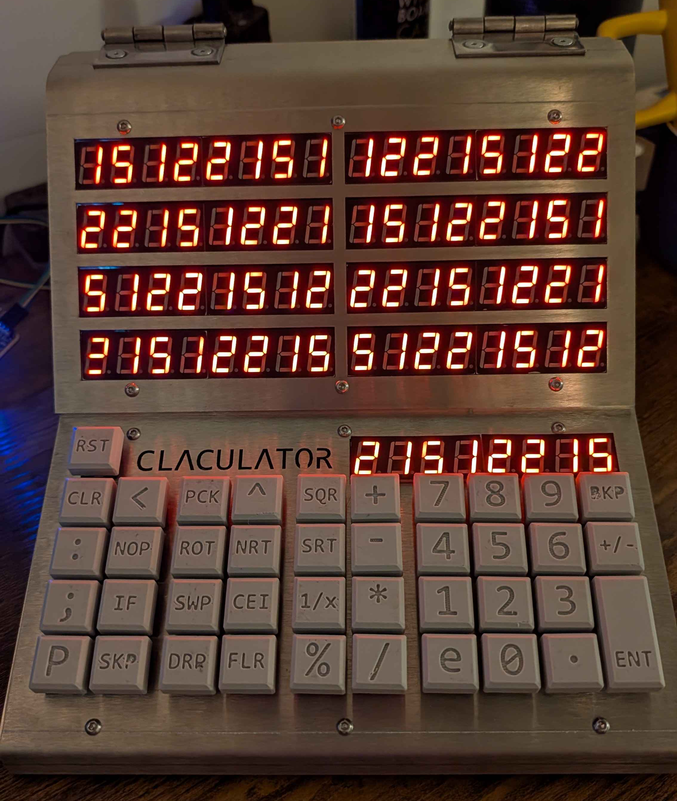
Fully assembled Claculator

Display

The seven-segment display board supports nine numeric displays, each with eight digits. It contains an SRAM chip which interfaces to the rest of the computer as a memory-mapped peripheral. When selected, the address and data bus is connected to the computer to be written to (but not read from) transparently. When the memory is not selected, a counter with a selectable clock source loops through each of the seventy-two digits, reads the corresponding byte from memory, and drives the corresponding digit using one bit for each segement (seven for the numeric part, one for the decimal point) with an array of P- and N-channel MOSFETs.

The front of the display, showing eight numeric displays
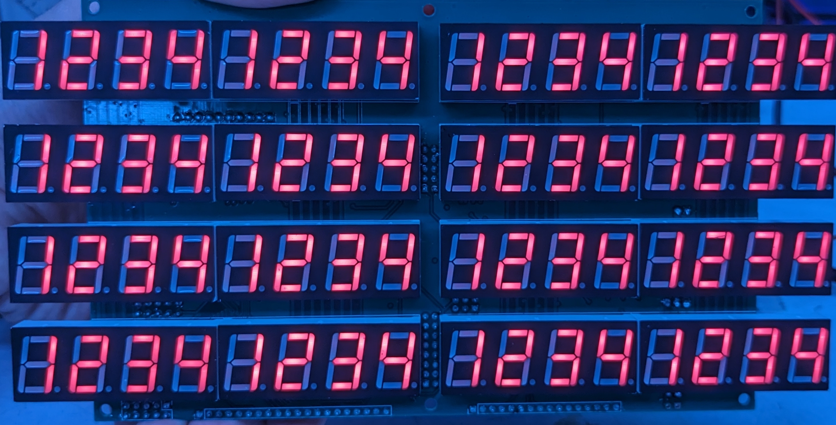
The front of the display, showing eight numeric displays

The back of the display, showing the logic and driver chips
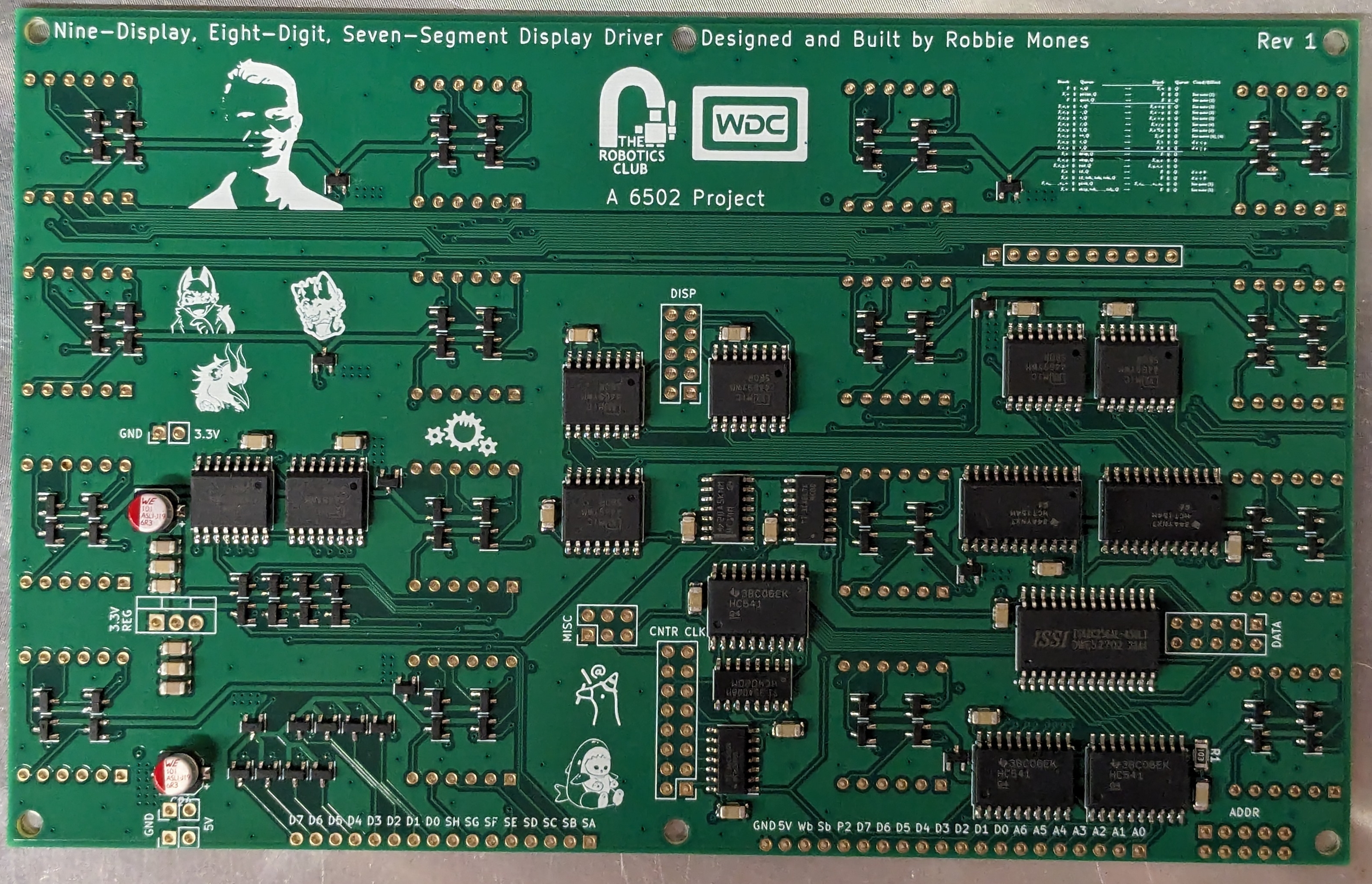
The back of the display, showing the logic and driver chips

Keypad

The keypad input board supports up to sixteen rows (5 are implemented), each with eight buttons. It detects rising edges of each button (equivalent to KeyDown events) with hardware RC debouncing and writes this information to a hardware FIFO buffer which is interfaced directly to the address and data bus of the system and can be configured to send an interrupt on new information in the buffer. It also has a header and location for a seven-segment display (not populated in these photos) as the ninth display that is driven from the display board.

The front of the keypad, showing five groups of eight keys
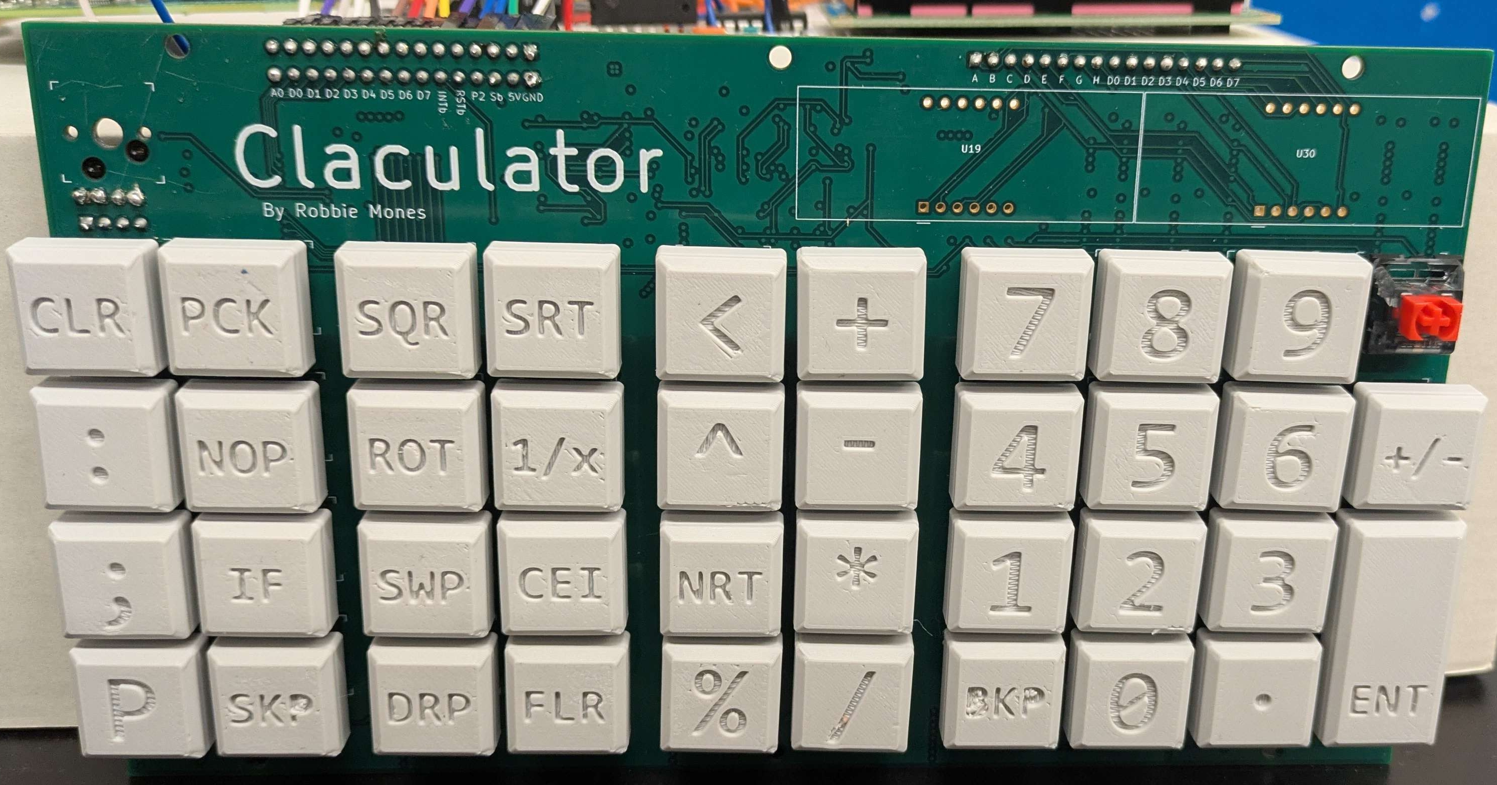
The front of the keypad, showing five groups of eight keys

The back of the keypad, showing the logic chips and hot-swappable key sockets
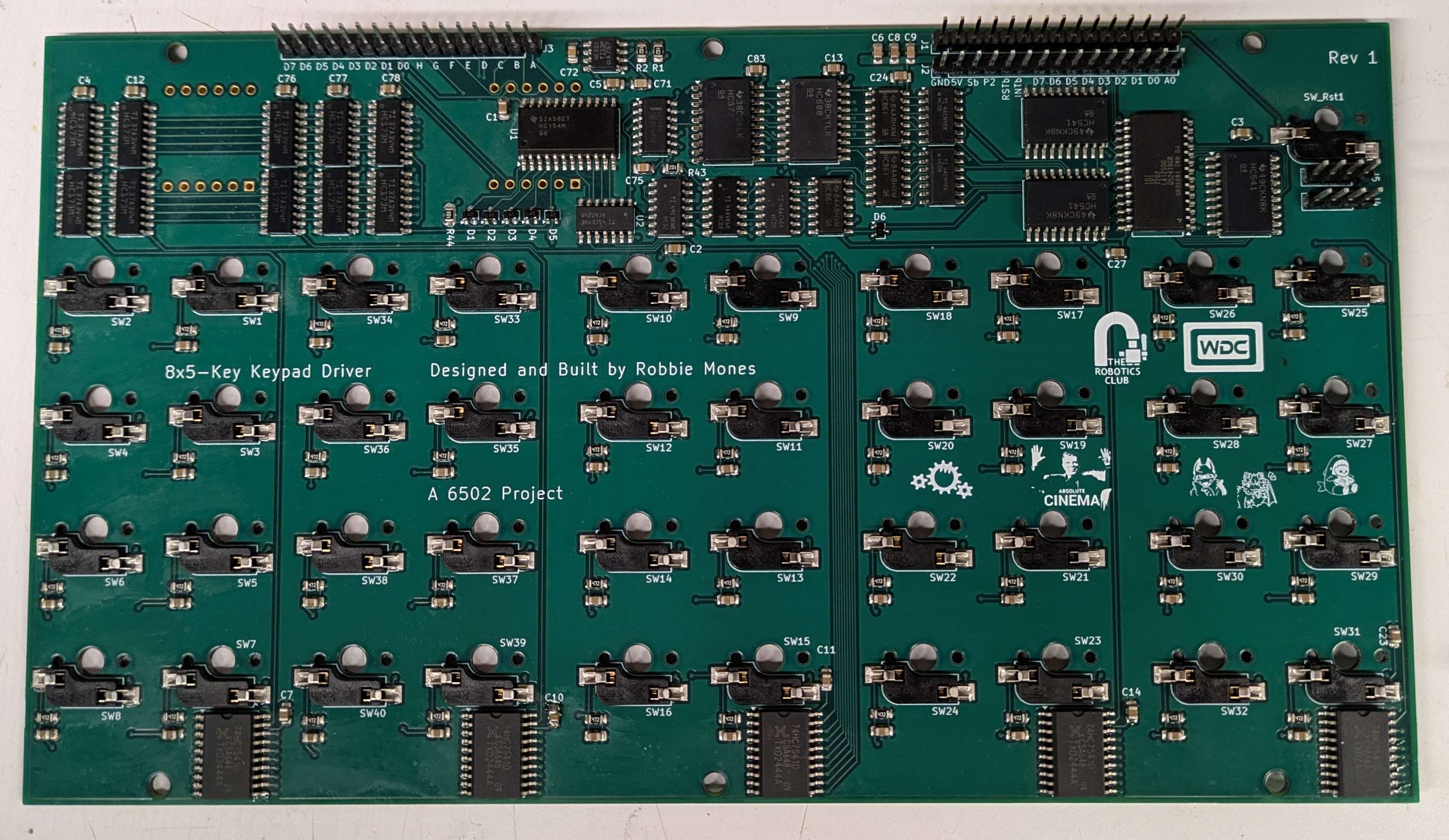
The back of the keypad, showing the logic chips and hot-swappable key sockets

Chassis

The chassis for the Claculator was manufactured by SendCutSend out of 1/8"-thick 304 stainless steel (except for the keypad plate which must be 0.06" thick to fit the keys). It has hinges at the top back to open the Claculator from the front to enable demonstrations and debugging more easily. It is very heavy (8lbs of sheet metal) and was very expensive but it's worth it for the bit.

Model of the assembled Claculator
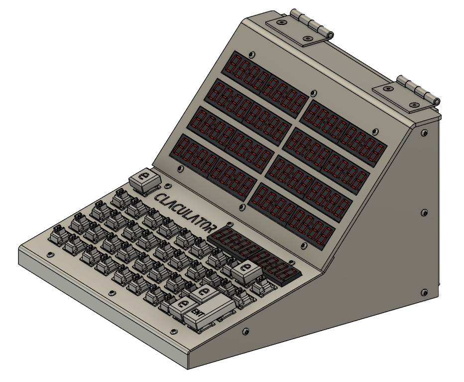
Model of the assembled Claculator

Code

I am currently working on some tests building up to a 32-bit integer mode to develop the RPN behavior and a feature-complete Clac implementation. After this, I will write a software 32-bit floating point implementation to support decimal arithmetic and comparisons. All of the code for this project will be written in 65C02 assembly.

Parts

202
QtyValueFootprintReferences
591uFCapacitor_SMD:C_0805_2012Metric_Pad1.18x1.45mm_HandSolderC1, C2, C10, C11, C12, C13, C14, C15, C16, C17, C18, C19, C20, C21, C22, C23 +43
41SW_Pushkeyswitches:Kailh_socket_MXSW1, SW2, SW10, SW11, SW12, SW13, SW14, SW15, SW16, SW17, SW18, SW19, SW20, SW21, SW22, SW23 +25
404.7kResistor_SMD:R_0805_2012Metric_Pad1.20x1.40mm_HandSolderR10, R11, R12, R13, R14, R15, R16, R17, R18, R19, R20, R21, R22, R23, R24, R25 +24
1074LS173Package_SO:SOIC-16_3.9x9.9mm_P1.27mmU7, U21, U23, U26, U28, U29, U36, U37, U38, U39
7LOGOLOGOG***, G***, G***, G***, G***, G***, G***
6DPackage_TO_SOT_SMD:SOT-323_SC-70D1, D2, D3, D4, D5, D6
574HC7541Package_SO:SOIC-20W_7.5x12.8mm_P1.27mmU12, U18, U20, U22, U27
31kResistor_SMD:R_0805_2012Metric_Pad1.20x1.40mm_HandSolderR1, R2, R43
374HC541Package_SO:SOIC-20W_7.5x12.8mm_P1.27mmU16, U17, U24
374HC86Package_SO:SOIC-14_3.9x8.7mm_P1.27mmU9, U10, U31
274HC08Package_SO:SOIC-14_3.9x8.7mm_P1.27mmU13, U14
2CC56-12EWADisplay_7Segment:CA56-12EWAU19, U30
2Conn_01x04_PinConnector_PinHeader_2.54mm:PinHeader_1x04_P2.54mm_VerticalJ4, J5
2Conn_01x15_PinConnector_PinHeader_2.54mm:PinHeader_1x15_P2.54mm_VerticalJ1, J2
10.1uFCapacitor_SMD:C_0805_2012Metric_Pad1.18x1.45mm_HandSolderC9
110kResistor_SMD:R_0805_2012Metric_Pad1.20x1.40mm_HandSolderR44
110nFCapacitor_SMD:C_0805_2012Metric_Pad1.18x1.45mm_HandSolderC72
110uFCapacitor_SMD:C_0805_2012Metric_Pad1.18x1.45mm_HandSolderC6
11nFCapacitor_SMD:C_0805_2012Metric_Pad1.18x1.45mm_HandSolderC75
120nFCapacitor_SMD:C_0805_2012Metric_Pad1.18x1.45mm_HandSolderC71
174HC00Package_SO:SOIC-14_3.9x8.7mm_P1.27mmU5
174HC02Package_SO:SOIC-14_3.9x8.7mm_P1.27mmU8
174HC14Package_SO:SOIC-14_3.9x8.7mm_P1.27mmU4
174HC154Package_SO:SOIC-24W_7.5x15.4mm_P1.27mmU1
174HC32Package_SO:SOIC-14_3.9x8.7mm_P1.27mmU6
174HC4024Package_SO:SOIC-14_3.9x8.7mm_P1.27mmU2
174HC688Package_SO:SOIC-20W_7.5x12.8mm_P1.27mmU11
174LS377Package_SO:SOIC-20W_7.5x12.8mm_P1.27mmU25
1Conn_01x16_PinConnector_PinHeader_2.54mm:PinHeader_1x16_P2.54mm_VerticalJ3
1IDT7202Package_SO:SOIC-28W_7.5x18.7mm_P1.27mmU15
1NE555DPackage_SO:SOIC-8_3.9x4.9mm_P1.27mmU3

More from Robert-Mones/Claculator

3
  • 4 layers174 × 109 mmClaculator Display, the printed circuit board in 3D

    Claculator Display

    Robert-Mones/Claculator

    A reverse Polish notation calculator with added features such as comparisons, branching, and custom recursive operators taken from the Clac project from the 15-122 course at Carnegie Mellon University.

    170 parts5
  • 4 layers68.5 × 43.5 mmPunchcard Reader, the printed circuit board in 3D

    Punchcard Reader

    Robert-Mones/Claculator

    A reverse Polish notation calculator with added features such as comparisons, branching, and custom recursive operators taken from the Clac project from the 15-122 course at Carnegie Mellon University.

    36 parts5
  • 6 layers16.5 × 21.6 mmClock Addon, the printed circuit board in 3D

    Clock Addon

    Robert-Mones/Claculator

    A reverse Polish notation calculator with added features such as comparisons, branching, and custom recursive operators taken from the Clac project from the 15-122 course at Carnegie Mellon University.

    7 parts5

Similar boards

  • 4 layers304.5 × 217.2 mmLatest Full Backplane, the printed circuit board in 3D

    Latest Full Backplane

    Trilobyte-CPU/8-bit-computer

    A DIY 8-bit computer built mostly with discrete logic chips

    478 parts2
  • 2 layers137.2 × 53.3 mmPs2, the printed circuit board in 3D

    Ps2

    scefrom/SF68

    A board featuring the Motorola 68000

    60 parts2
  • 2 layers200 × 150 mmMicro, the printed circuit board in 3D

    Micro

    jurendono/VMC

    A Versitile 6502 Based Microcomputer

    235 parts
  • 2 layers299.7 × 198.1 mmCisc-8, the printed circuit board in 3D

    Cisc-8

    nailed-barnacle/Cisc-8-ttl-processor

    A cut-down version of the 8080 processor using HCTTL and including a discrete ALU and instruction decoder

    319 parts1MIT
  • 2 layers180 × 67.5 mmNEW KANJI ROM, the printed circuit board in 3D

    NEW KANJI ROM

    bml3mk5/S1KanjiRomJIS2

    JIS Level 2 Kanji ROM Card for HITACHI MB-S1

    61 parts
  • 4 layers100 × 100 mmControllerBoard, the printed circuit board in 3D

    ControllerBoard

    nunosousa/TelescopeMirrorTester

    This is an application intended to provide useful tools to perform Foucault or Wire testing on reflective telescope mirrors

    116 partsMIT
  • 2 layers177.8 × 130.8 mmDurango, the printed circuit board in 3D

    Durango

    zuiko21/minimOS

    Scalable OS for 6502/65816

    159 parts23MIT

Questions

How big is the Claculator Keypad PCB?

It measures 210 × 119 mm and has 6 copper layers, 1.6 mm thick.

What parts does the Claculator Keypad use?

202 parts, built around the 74HC7541D, 74HC541D, 74LS173SC and 74HC86D. The full list of its parts is on this page, with links to each part's symbol and footprint where PCBKit's library has them.

Where can I download the Claculator Keypad KiCad files?

From the Robert-Mones/Claculator repository on GitHub, at the commit this page was made from: the board is Claculator_Keypad/Claculator_Keypad.kicad_pcb and its schematic Claculator_Display/Claculator_Display.kicad_sch. PCBKit opens the board in the browser, with nothing to install.

Can I use the Claculator Keypad design in my own project?

Its repository states no licence, so its author keeps all rights: ask Robert-Mones before reusing the design.