

2 layers333.4 × 149.9 mm

 hansonxiex-stack/nrf52-th-sensor-hardware
BLE temperature and humidity sensor (nrf52 + SHT40)
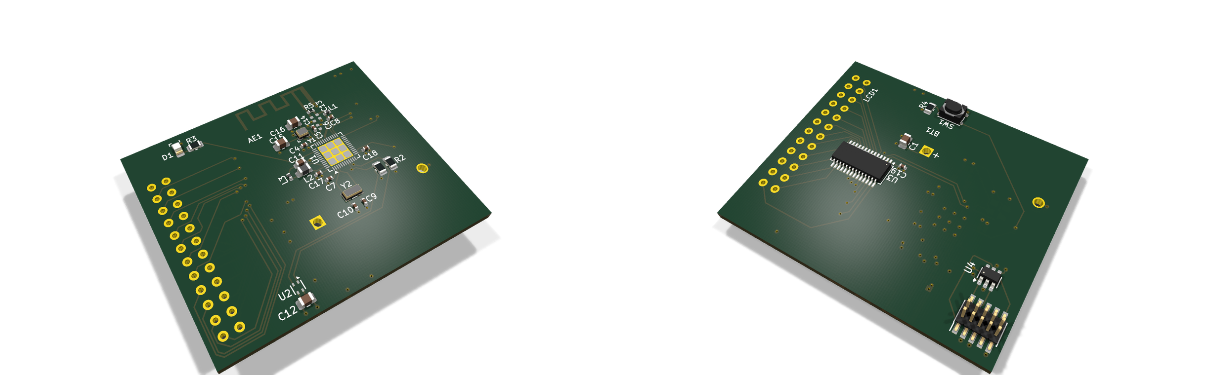
Smart th sensor is an open-source printed circuit board by hansonxiex-stack, from the hansonxiex-stack/nrf52-th-sensor-hardware repository on GitHub. It is a 4-layer board of 48.2 × 40 mm with 37 parts on 77 nets, routed with 353 tracks and 65 vias.
It is built around the TT0554TLX and CR2032. Its parts include 17 capacitors, 5 resistors, 4 ICs, 3 inductors and 2 crystals. It belongs with the sensors and measurement and radio and wireless boards and the nRF52 and nRF5x boards of this library.
基于 nRF52810 的低功耗 BLE 温湿度传感器:CR2032 纽扣电池直接供电,SHT40 采集温湿度,HT16C21A 驱动段码 LCD 常显,板载 2.4 GHz PCB 天线对外广播。
工程从需求分析、原理图、四层 PCB 布局布线,做到电源仿真、信号/电源完整性分析、热设计、DFM 整改与生产文件交付,完整走完一遍从需求到制造文件的硬件设计流程。
本工程只做设计、仿真与可制造性分析,未提交订单、未产生实际支付。 文档中出现的板厂报价截图均为下单页快照,用于比较工艺选项的成本,不代表已下单。
| 项目 | 参数 |
|---|---|
| 板框尺寸 | 48.25 × 40.05 mm |
| 层数 / 叠层 | 4 层,S-G-P-S(信号-地-电源-信号) |
| 板厚 | 1.6062 mm(成品 1.6 mm 级) |
| 主控 | nRF52810 QFN48,0.4 mm 间距 |
| 传感器 | SHT40(I²C,±1.8 %RH / ±0.2 °C) |
| 显示 | HT16C21A + 20×4 段码 LCD |
| 供电 | CR2032 3.0 V 直供,不经 LDO |
| 无线 | 2.4 GHz 板载 PCB 天线,50 Ω 馈线 W ≈ 0.36 mm |
| I²C | 100 kHz,10 kΩ 上拉 |
| 低电量阈值 | 2.8 V 告警;系统工作下限 2.4 V |
| BOM | 23 行 / 31 个位号,标准带屏版约 28.36 元 |
| DRC | 0 error、0 未连接 |
        ┌──────────┐   I²C    ┌────────────┐
 CR2032 ─┤ SHT40    ├──────────┤ nRF52810   ├── SWD ── J1(U4 ESD 保护)
  3.0 V  └──────────┘          │            │
                              │            ├── 2.4 GHz PCB 天线
                     I²C      │            │
        ┌────────────┐        │            │
        │ HT16C21A   ├────────┴────────────┘
        │     ↓      │
        │  段码 LCD  │
└────────────┘三条路径:数据(SHT40 → nRF52810 → 段码 LCD、天线)、供电(CR2032 直供三个模块)、调试(SWD 三线,入口处 U4 做 ESD 保护)。
.
├── hardware/          KiCad 10 工程、自定义符号与封装、ERC/DRC 报告
├── simulation/        LTspice 电源仿真电路与运行日志
├── manufacturing/     生产文件包(Gerber、钻孔、BOM、CPL、制板说明)
├── docs/              8 周实验报告与各专项设计说明(Markdown)
├── presentation/      项目演示 PPT(含逐页讲解录音)、PDF 与讲解稿
└── images/ 3D 图、系统框图、流程框图、关键布局图各目录下的文件命名即对应周次与主题,docs/wk1 … docs/wk8 按八周实验顺序排列。
叠层与阻抗 — 采用 S-G-P-S 四层结构。顶层射频馈线以下方地平面(In1.GND)为参考,按介质厚度 0.2104 mm、Er ≈ 4.4 反算 50 Ω 对应线宽约 0.36 mm;QFN 引脚出口受焊盘间距限制,局部采用约 0.7 mm 的短颈缩,其余馈线保持顶层连续、避免过孔。
布局分区 — 射频链路单独占一角并保持参考地完整;SHT40 布置在板边、与主控中心距离约 25.5 mm,器件下方设置四层禁铜区,降低板内热耦合;晶振与负载电容贴近对应引脚,去耦电容结合电源引脚布置。
电源完整性 — CR2032 直供省掉 LDO 压差损失。LTspice 中以电压源+电池内阻+等效脉冲负载+去耦电容建模,扫描 10 / 30 / 50 Ω 三档内阻,最低电压约 2.499 V;PCB 自身压降小于 0.5 mV,电压波动主要来自电池内阻。
接口与防护 — I²C 综合驱动供电条件采用 100 kHz,按约 30 pF 总线电容估算上升时间约 254 ns;SHT40 与 HT16C21A 地址不冲突,共用一路总线。SWD 入口 U4 在保护性能与低功耗之间取舍,重点控制漏电流。
可制造性 — DRC 收口到 0 error、0 未连接;DFM 报出的 96 条危险按封装模型差异、贴装方向与盘中孔工艺逐条分类核对,U1 散热盘盘中孔在制板说明中明确采用 POFV 工艺(IPC-4761 Type VII)。
| 环节 | 工具 |
|---|---|
| 原理图 / PCB | KiCad 10.0 |
| 电源仿真 | LTspice |
| 阻抗计算 | 板厂阻抗计算器 + 手工反算交叉验证 |
| 可制造性 | 板厂 DRC / DFM 分析 + 人工逐条核对 |
| 文档 | 内容 |
|---|---|
docs/项目理解与个人8周计划 | 项目理解与八周安排 |
docs/变更记录表_智能温湿度传感器 | 全流程变更与决策记录 |
docs/wk1 | 产品需求分析、引脚分配 |
docs/wk2 | 器件选型、符号库、LTspice 入门 |
docs/wk3 | 四层叠层设计与阻抗计算 |
docs/wk4 | 布局布线 |
docs/wk5 | DRC、ESD 与滤波、电源模块布线 |
docs/wk6 | 信号完整性、电源完整性、热设计、DFT |
docs/wk7 | DFM、BOM 与工艺、生产文件包清单、贴装方向说明 |
docs/wk8 | 项目总结报告、交付确认说明 |
presentation/项目演示PPT_讲解稿 | 22 页演示的逐页讲稿 |
| Qty | Value | Footprint | References |
|---|---|---|---|
| 5 | 100n | Capacitor_SMD:C_0402_1005Metric | C4, C7, C17, C18, C19 |
| 3 | 10k | Resistor_SMD:R_0805_2012Metric | R1, R2, R4 |
| 2 | 12p | Capacitor_SMD:C_0402_1005Metric | C9, C10 |
| 2 | 12pF | Capacitor_SMD:C_0805_2012Metric | C15, C16 |
| 2 | DNP | Capacitor_SMD:C_0402_1005Metric | C13, C14 |
| 1 | 0 | Resistor_SMD:R_0402_1005Metric | R5 |
| 1 | 0.8p | Capacitor_SMD:C_0402_1005Metric | C8 |
| 1 | 1.0u | Capacitor_SMD:C_0603_1608Metric | C11 |
| 1 | 100n | Capacitor_SMD:C_0805_2012Metric | C12 |
| 1 | 100p | Capacitor_SMD:C_0402_1005Metric | C5 |
| 1 | 10u | Inductor_SMD:L_0805_2012Metric | L2 |
| 1 | 15n | Inductor_SMD:L_0402_1005Metric | L3 |
| 1 | 2.2k | Resistor_SMD:R_0805_2012Metric | R3 |
| 1 | 2.2u | Capacitor_SMD:C_0805_2012Metric | C1 |
| 1 | 3.9n | Inductor_SMD:L_0402_1005Metric | L1 |
| 1 | 32.768k | Crystal:Crystal_SMD_3215-2Pin_3.2x1.5mm | Y2 |
| 1 | 32M | Crystal:Crystal_SMD_2016-4Pin_2.0x1.6mm | Y1 |
| 1 | Antenna_Shield | RF_Antenna:Texas_SWRA117D_2.4GHz_Left | AE1 |
| 1 | CR2032 | Battery:BatteryHolder_MYOUNG_BS-07-A1BJ001_CR2032 | BT1 |
| 1 | Conn_02x05_Odd_Even | Connector_PinHeader_1.27mm:PinHeader_2x05_P1.27mm_Vertical_SMD | J1 |
| 1 | HT16C21A | Package_SO:SSOP-28_3.9x9.9mm_P0.635mm | U3 |
| 1 | N.C. | Capacitor_SMD:C_0402_1005Metric | C6 |
| 1 | SHT40 | Sensor_Humidity:Sensirion_DFN-4_1.5x1.5mm_P0.8mm_SHT4x_NoCentralPad | U2 |
| 1 | STATUS_LED | LED_SMD:LED_0805_2012Metric_Pad1.15x1.40mm_HandSolder | D1 |
| 1 | SW_Push | Button_Switch_SMD:SW_SPST_PTS810 | SW1 |
| 1 | TT0554TLX | Package_TO_SOT_SMD:SOT-23-6 | U4 |
| 1 | nRF52810-QFxx | Package_DFN_QFN:QFN-48-1EP_6x6mm_P0.4mm_EP4.6x4.6mm | U1 |
| 1 | ~ | custom_fp:LCD_Segment_20x4 | LCD1 |


skiselev/zeta_sbc
Zeta SBC is an Zilog Z80 based single board computer. It is inspired by Ampro Little Board Z80 and N8VEM project. Zeta SBC is software compatible with RomWBW Firmware
It measures 48.2 × 40 mm and has 4 copper layers, 1.61 mm thick.
37 parts, built around the TT0554TLX and CR2032. The full list of its parts is on this page, with links to each part's symbol and footprint where PCBKit's library has them.
From the hansonxiex-stack/nrf52-th-sensor-hardware repository on GitHub, at the commit this page was made from: the board is hardware/smart-th-sensor.kicad_pcb and its schematic hardware/smart-th-sensor.kicad_sch. PCBKit opens the board in the browser, with nothing to install.
Its repository states no licence, so its author keeps all rights: ask hansonxiex-stack before reusing the design.