
2 layers208 × 130 mm

 Hackuarium/ion-mobility11
DIY Ion mobility spectrometer
DividerV2 is an open-source printed circuit board by Hackuarium, from the Hackuarium/ion-mobility repository on GitHub. It is a 2-layer board of 227.8 × 48 mm with 100 parts on 68 nets, routed with 110 tracks and 0 vias.
It is built around the SFH617A-1. Its parts include 62 resistors, 4 connectors, 3 capacitors and 1 IC.
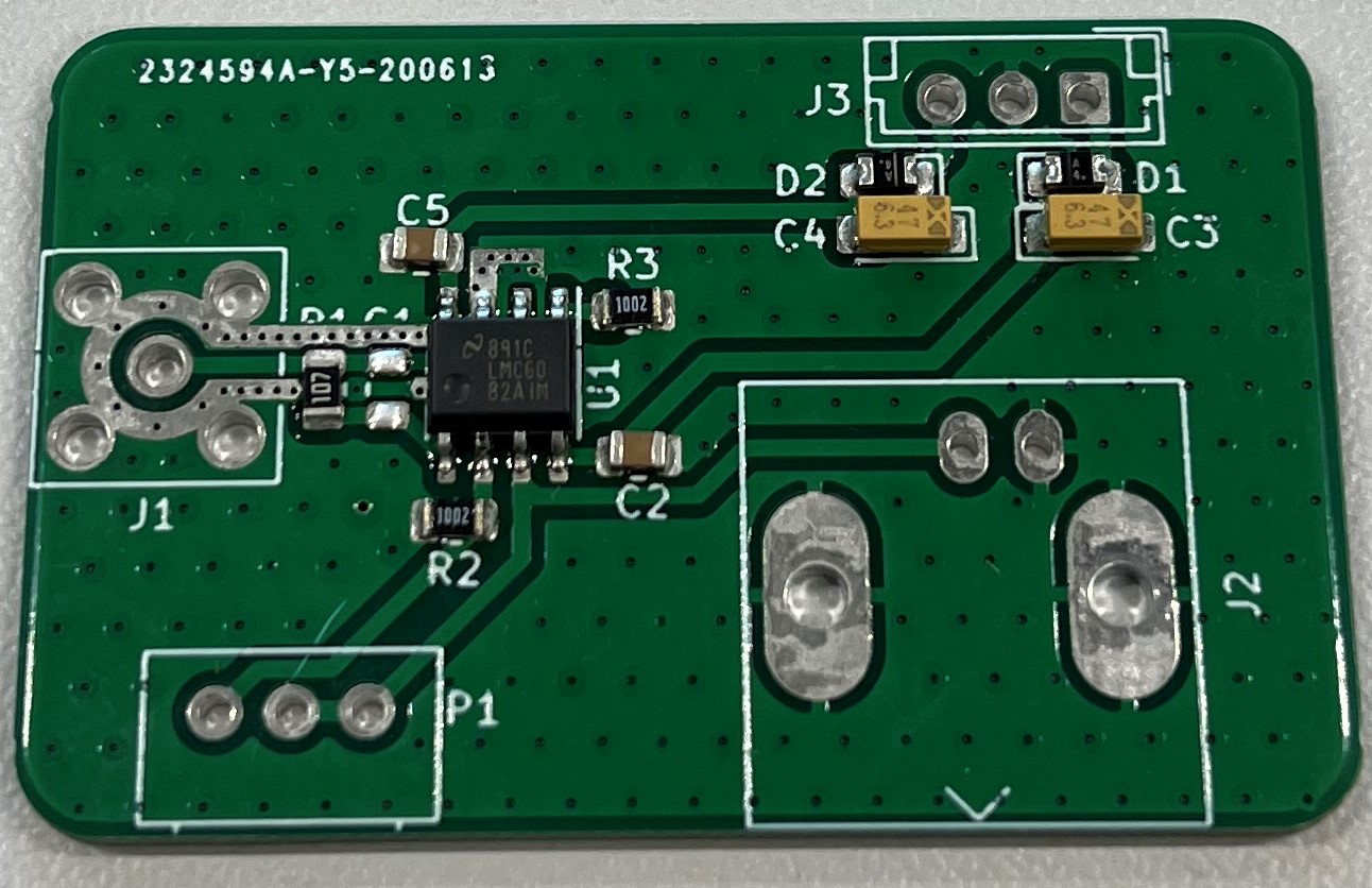
Amplification stage to transform the small current on the target to an acceptable voltage to be read/processed.
Transimpedance circuit with a big gain (10^8) and a voltage follower through a dual precision operationnal amplifier (Texas Instruments LMC6082).
The circuit needs to be as close as possible to the target of the IMS in order to limit the noise present on the signal. One possibility is to solder the PCB directly on the back of the target.
Possible amplification of the noise must be taken into account, and possibly filtered through a very small capacitor (~0.01 pF, thus quite expensive) in the gain stage feedback loop (a bigger resistor amplifies the signal but also the noise).
Below is a picture of the mounted PCB, currently missing the connectors and a potential filtering capacitor C1.
| Qty | Value | Footprint | References |
|---|---|---|---|
| 29 | 10M | Resistor_SMD:R_1206_3216Metric_Pad1.42x1.75mm_HandSolder | R1, R2, R10, R11, R12, R13, R14, R15, R16, R17, R18, R19, R20, R21, R22, R23 +13 |
| 29 | 10M | Resistor_SMD:R_1206_3216Metric | R34, R35, R36, R37, R38, R39, R40, R41, R42, R43, R44, R45, R46, R47, R48, R49 +13 |
| 29 | Electr. | Connector:Pad_for_electrode | E1, E2, E10, E11, E12, E13, E14, E15, E16, E17, E18, E19, E20, E21, E22, E23 +13 |
| 3 | 4700pF 10kV | Capacitor_THT:C_Rect_L13.0mm_W8.0mm_P10.00mm_FKS3_FKP3_MKS4 | C1, C2, C3 |
| 2 | 1.5M | Resistor_SMD:R_1206_3216Metric | R31, R33 |
| 2 | 10kV | Connector_Pin:Pin_D1.4mm_L8.5mm_W2.8mm_FlatFork | J2, J4 |
| 1 | 0V | Connector_Pin:Pin_D1.4mm_L8.5mm_W2.8mm_FlatFork | J3 |
| 1 | 100M | Potentiometer_THT:Potentiometer_ACP_CA14-H4_Horizontal | RV1 |
| 1 | 100M | Resistor_SMD:R_1206_3216Metric | R32 |
| 1 | 15kV | Connector_Pin:Pin_D1.4mm_L8.5mm_W2.8mm_FlatFork | J1 |
| 1 | 500K | Resistor_THT:R_Axial_DIN0207_L6.3mm_D2.5mm_P15.24mm_Horizontal | R30 |
| 1 | SFH617A-1 | Package_DIP:DIP-4_W7.62mm | U1 |
It measures 227.8 × 48 mm and has 2 copper layers, 1.6 mm thick.
100 parts, built around the SFH617A-1. The full list of its parts is on this page, with links to each part's symbol and footprint where PCBKit's library has them.
From the Hackuarium/ion-mobility repository on GitHub, at the commit this page was made from: the board is PCB/Divider/DividerV2/DividerV2.kicad_pcb. PCBKit opens the board in the browser, with nothing to install.
Its repository states no licence, so its author keeps all rights: ask Hackuarium before reusing the design.


IdahoLabResearch/AcCCS
A collection of tools and scripts used to communicate and emulate Electric Vehicle Communication Controllers (EVCC) and Supply Equipment Communication Controllers (SECC).

bildschirmtext/rpi-dbt03
Hardware, Software and Firmware for a Raspberry Pi to DBT-03 adapter

lal12/vaillant-heater-control-esp
This project contains a little board (and software) to control a Vaillant heater.

LSUTigerRacing/Electronics
This repository contains all of the KiCad Schematics for the 2026 TigerRacing Formula SAE's Electronics Subsystem.

bhaskar9980/Guardian
Guardian is an advanced, fully automated hydroponics system designed to optimize plant growth and maximize yield.

JacobParent7/FSAE_ELECTRONICS
Repository for Fault Latch, BSPB, TSIL (TSSI) , TSAL (RML),

Majklzbastlirny/WeatherStation
Weather Station with ESP32, ESP8266, MQTT and Grafana

ucsbieee/Tesla-Coil-MIDI-Synth
Convert MIDI to pulses to drive our DRSSTC