


2 layers39 × 49.5 mm

 bhaskar9980/Guardian5
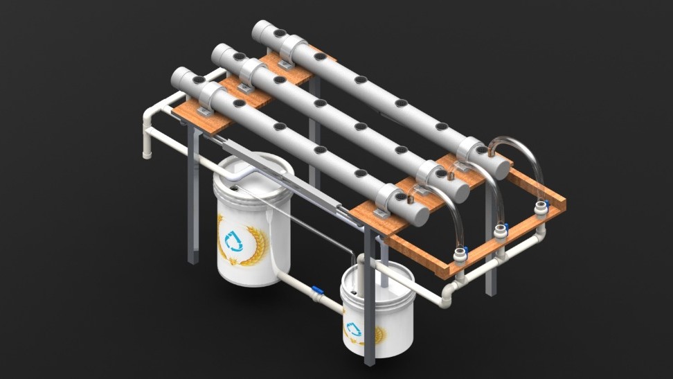
Guardian is an advanced, fully automated hydroponics system designed to optimize plant growth and maximize yield. Utilizing micro-controllers and pH fuzzy logic control, it ensures precise nutrient delivery, enables remote monitoring, and achieves remarkable water savings while increasing crop productivity.
Arduino relay is an open-source printed circuit board by bhaskar9980, from the bhaskar9980/Guardian repository on GitHub, published under the MIT licence. It is a 2-layer board with 58 parts on 42 nets, routed with 329 tracks and 0 vias.
It is built around the DHT11, SFH617A-1 and BC547. Its parts include 18 resistors, 11 connectors, 4 ICs, 4 diodes and 4 transistors. It belongs with the home automation and IoT boards and the ESP32 and AVR (ATmega, ATtiny) boards of this library.

Guardian is an advanced, fully automated hydroponics system designed to optimize plant growth and maximize yield. Utilizing micro-controllers and pH fuzzy logic control, it ensures precise nutrient delivery, enables remote monitoring, and achieves remarkable water savings while increasing crop productivity.
A Few Pictures of FireBase
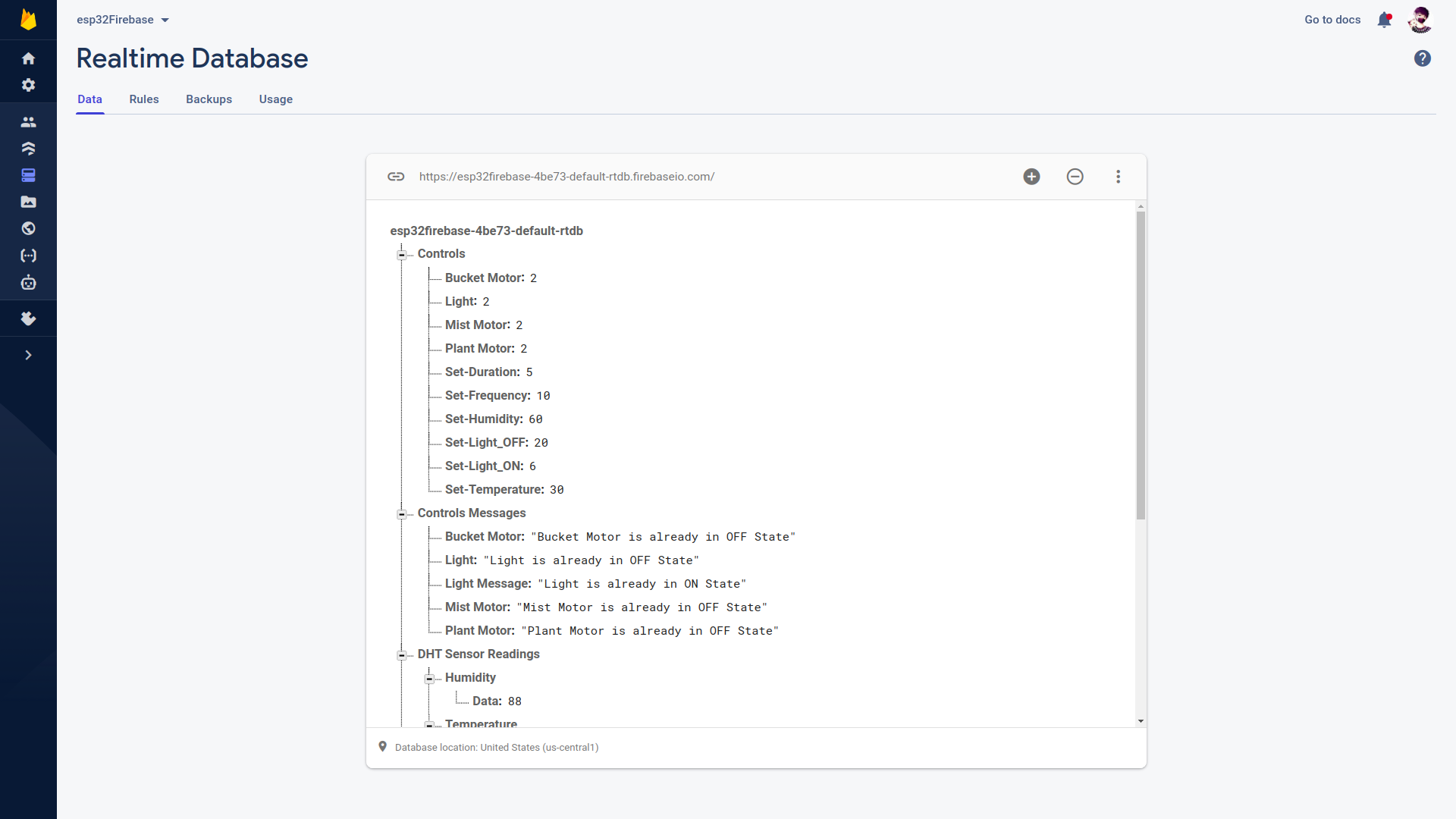
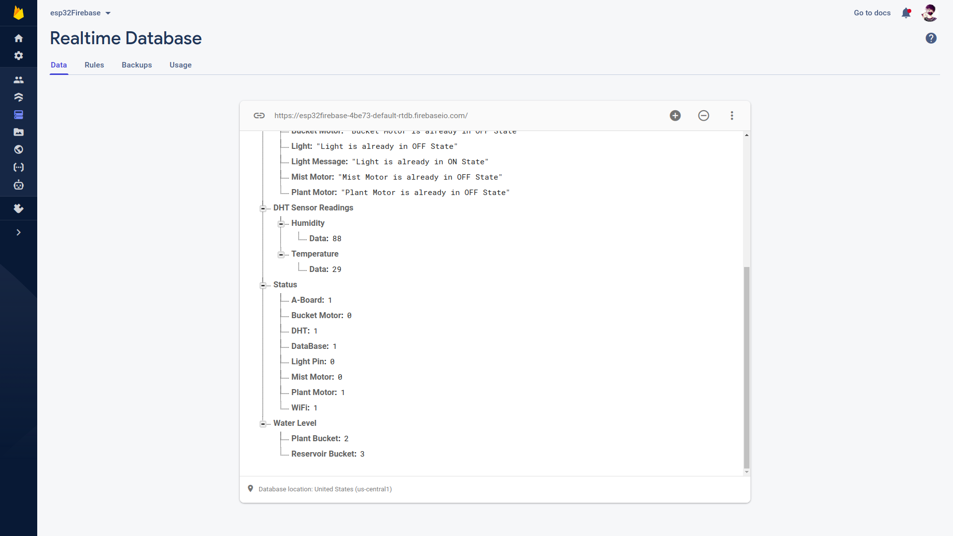
There are two Modes for Controlling the Motors and lighting
| Digits | Status | Mode |
|---|---|---|
| 0 | Off | Manual Override Mode ON |
| 1 | On | Manual Override Mode ON |
| 2 | - | Manual Override Mode OFF |
We can Manually Control/ Automate the Threshold Values of Humidity and Temperature as per the crop
We can Manually control/ Automate the Intervals of Lighting to control the Temperature as per the requirements of the crop
We can Manually control/ Automate the Intervals of running Plant Motor for regular watering as per the requirements of the crop
The Schematic and PCB designs are made using KiCAD. Find the files here: KiCad_PCB_design
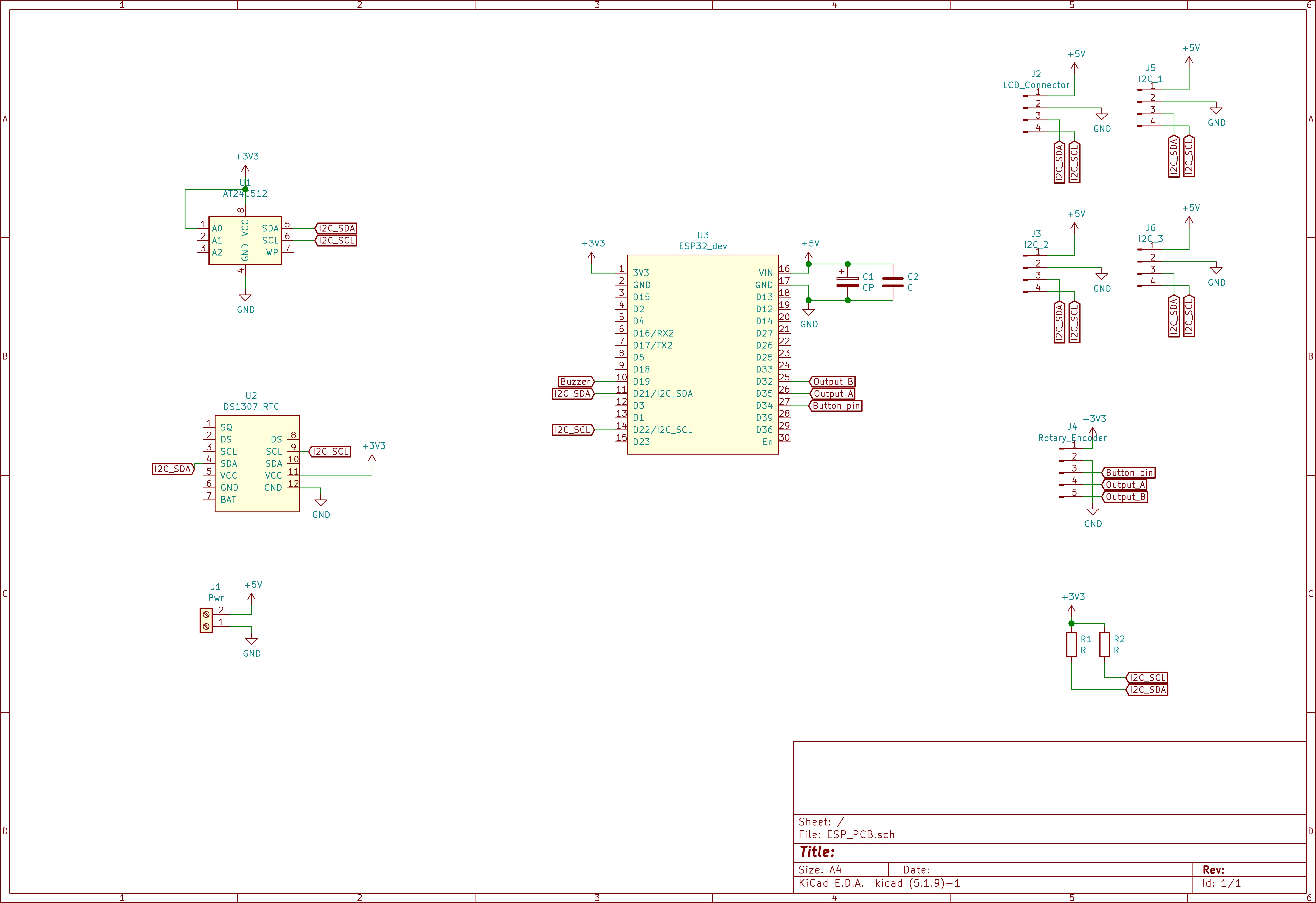
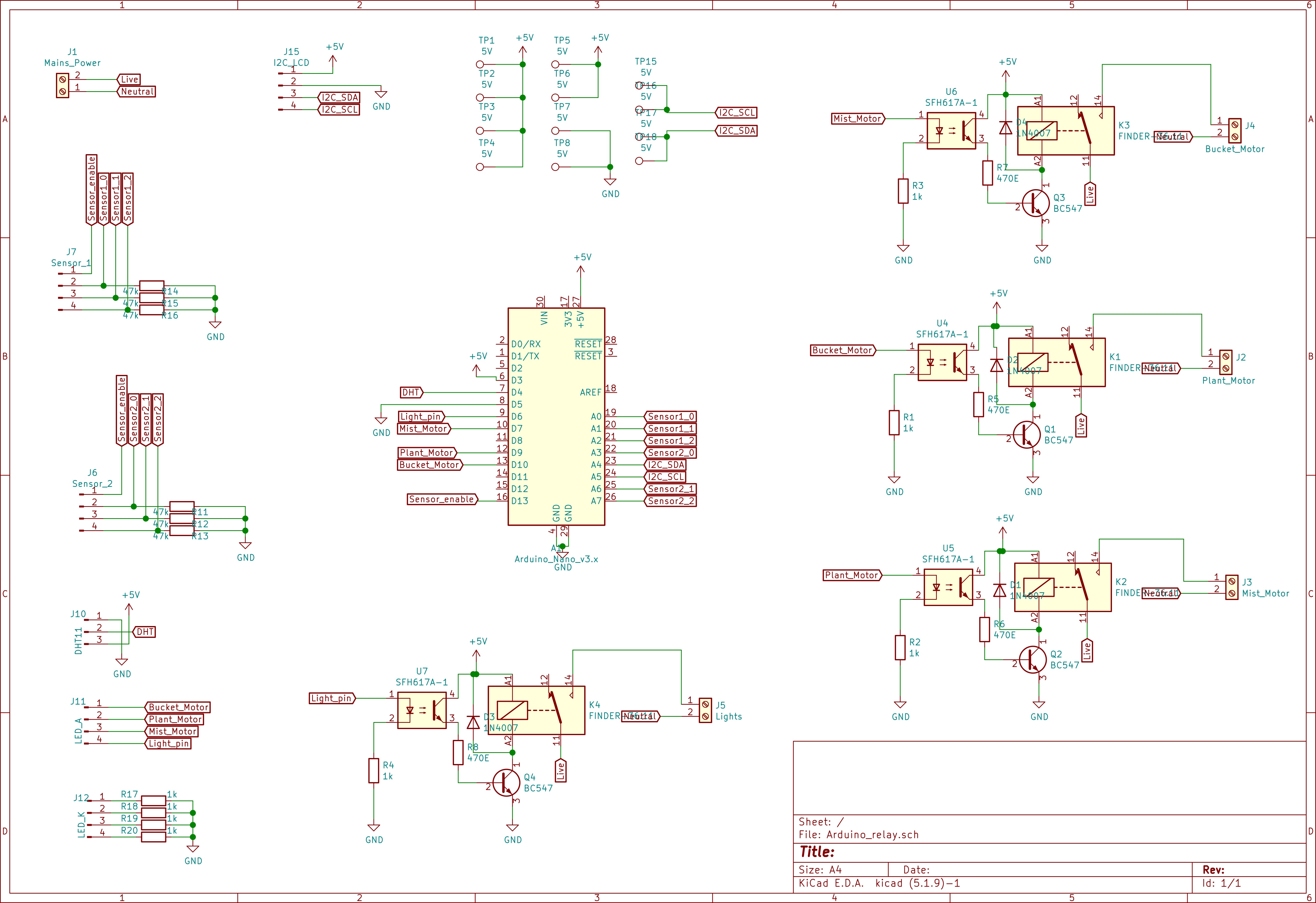
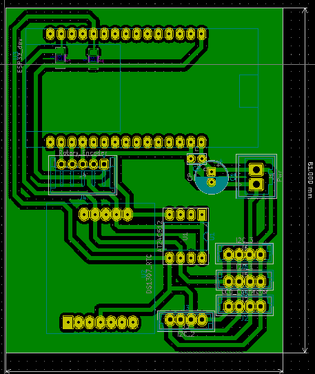
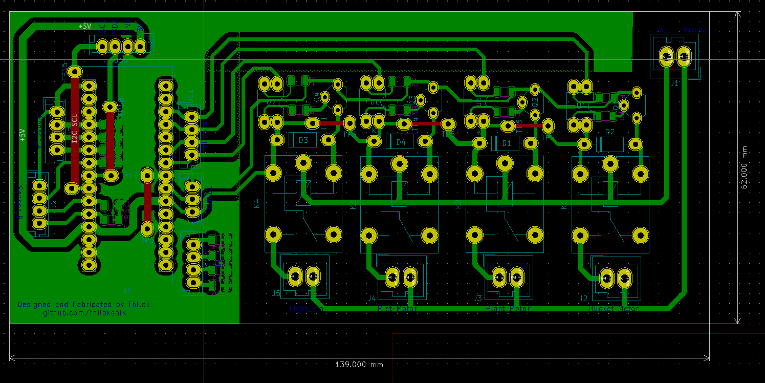
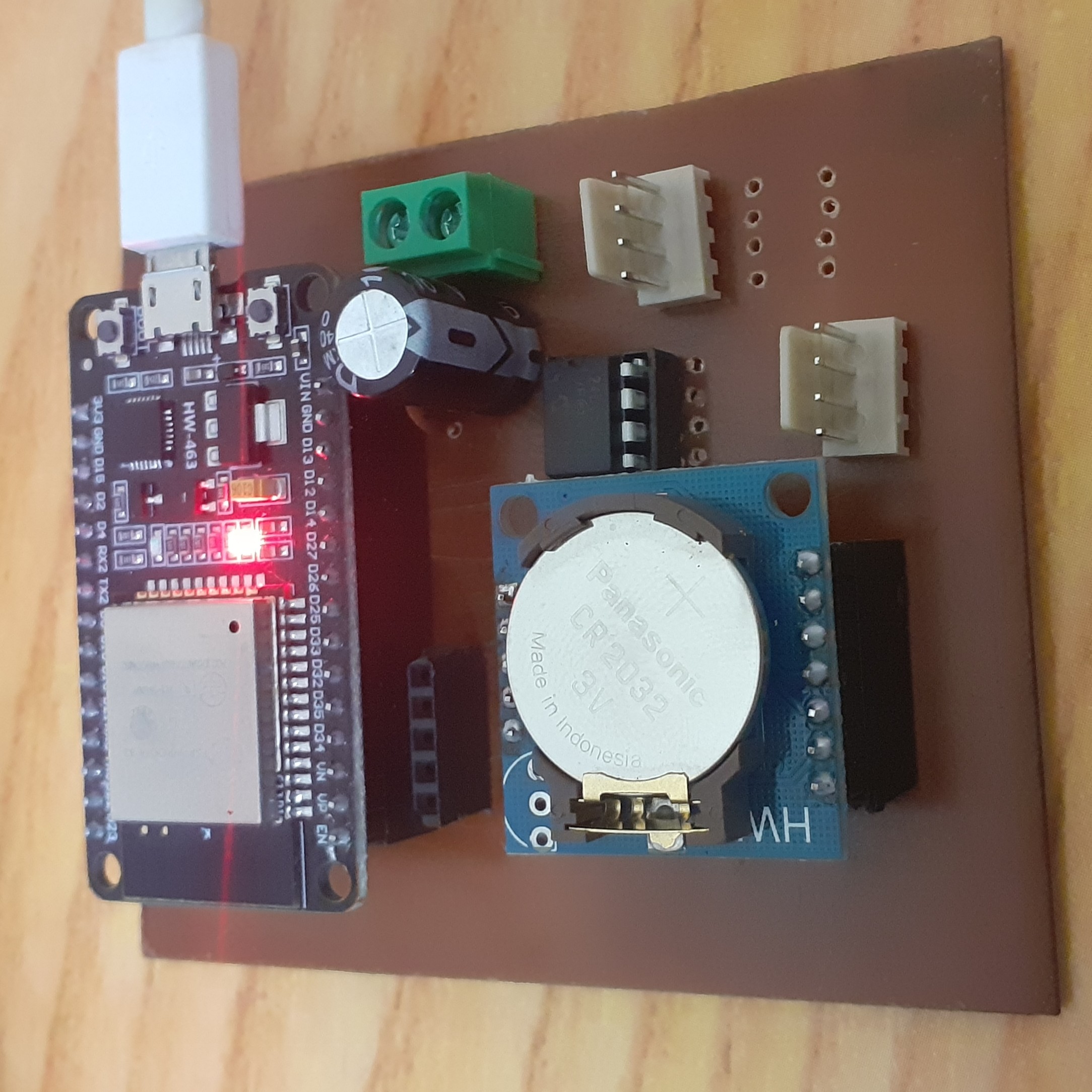
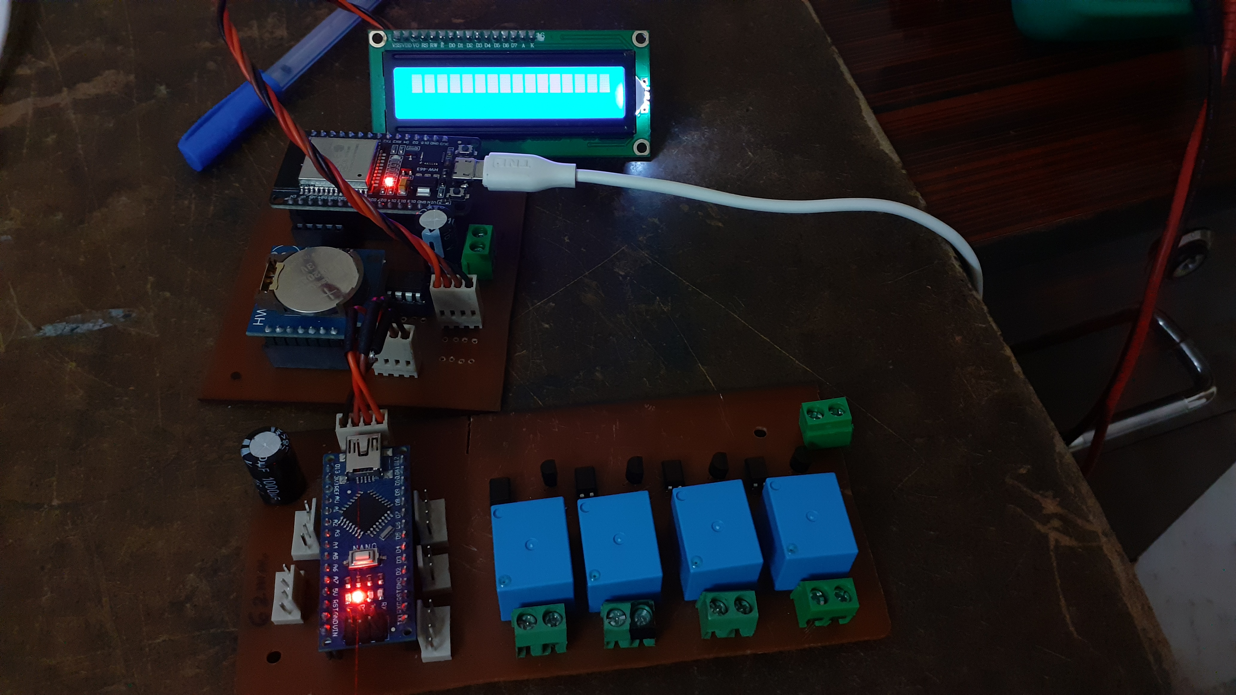
Find more pictures in Images folder
I2CSB libraryThis Arduino compatible library is made to simplify the communication paradigm that happens between master ESP32 and slave Arduino Nano.
I2CSB stands for I2C Slave board
The slave arduino nano does the following:
You can fetch the slave code here Arduino_slave.ino
The Master ESP32 can access these function using the I2CSB Library. As the name suggests the communication happens in I2C protocol.
To use the library just navigate to I2CSB and download it as zip file. Later in arduino IDE add this library using library manager and get started with the library using examples.
#define Slave_address 0x2F
I2CSB DB1(Slave_address);
Initialize the I2C communication by calling Wire.begin()
The library has following functions
| Function name | What is returned | return type | Arguments |
|---|---|---|---|
| 1. isConnected() | true if slave is connected | bool | no arguments |
| 2. getLevel() | Level encoded in single byte | byte | no arguments |
| 3. getTemperature() | Temperature | int | no arguments |
| 4. getHumidity() | Humidity | int | no arguments |
| 5. setOutputs() | True if the outputs are set correctly False if fails to set | bool | 4 bool variables |
The library also can monitor communication error or Miscommunication took place. This is how:
isConnected() function the master sends a request to get water level. If there is no error in the received information then the function returns True. In the event of death of slave or the slave is not connected or there is a communication error the function returns False.getLevel() function the return type is byte and the encoded level information in the byte is as follows x LA2 LA1 LA0 0 LB2 LB2 LB0 Here LA2,1,0 are points in sensor A and LB2,1,0 are points in Level B sensor. The x bit carries the error information. If there is no error in the communication then x = 1 else x = 0.getTemperature() function then return type is integer. And the DHT11 sensor can measure the temperatures between 0 to 60degC with a resolution of 1degC. So the information we get out of the sensor can never hit negative temperature. So the function returns -10 if there is any error and returns value between 0 and 60 if there is no error.getHumidity() function, the return type is int and has values between 20 to 80. so if there is any error then the returned value will be -10.True if there is no error in communication as well as the outputs are set as expected.
The arguments in setOutputs() function is in this order setOutputs(BucketMotor, PlantMotor, MistMotor, LightPin)| Function name | Sent Byte | Received bytes |
|---|---|---|
| 2. getLevel() | 0xAA | 0xAA 0xYY 0xYY |
| 3. getTemperature() | 0xCA | 0xCA 0xYY 0xYY |
| 4. getHumidity() | 0x5c | 0x5C 0xYY 0xYY |
| 5. setOutputs() | 0x60 | 0x60 0xYY 0xYY |
| 1. isConnected() | 0xAA | 0xAA 0xYY 0xYY |
isConnected() function is same as getLevel() function with a different data type. Because I was This library can be used as a base to make any type of simple arduino I2C slave device.
Find the database library here DataBase.
The data structure:
| Data | Bytes taken | Range |
|---|---|---|
| Day, Hour, Minute in the month | 2 bytes | 44640 |
| Temperature | 1 byte | 0 to 60 degC |
| Humidity | 1 byte | 20 to 80% |
| Level Array | 1 byte | 0x00 to 0x77 |
| Address | Data |
|---|---|
| 0 , 1 | Address pointer |
| 2 - 6 | Data set 1 |
| 7 - 11 | Data set 2 |
| 12 - 16 | Data set 3 |
| (5n-3) - (5n+1) | Data set n |
The library offers following functions:
| Function name | arguments | return value |
|---|---|---|
| storeAt | EEPROM Object, Address, Day, Hour, Minute, Temperature, Humidity, Waterlevel array | void type |
| resetAddress | EEPROM Object | void |
| getDataAt | EEPROM Object, Address, Data-literal | Data |
| getNextAddress | EEPROM Object | Address of next Dataset to be written |
| resetAddress | EEPROM Object | resets the address pointer to initial value |
I2C_eeprom ee(0x50, I2C_DEVICESIZE_24LC512);DataBase DB;ee using ee.begin().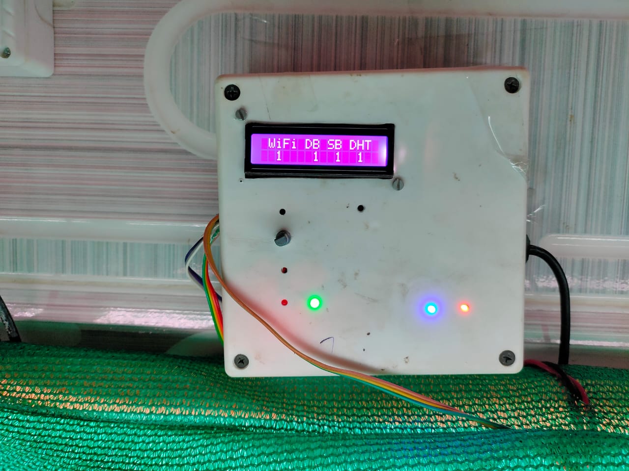
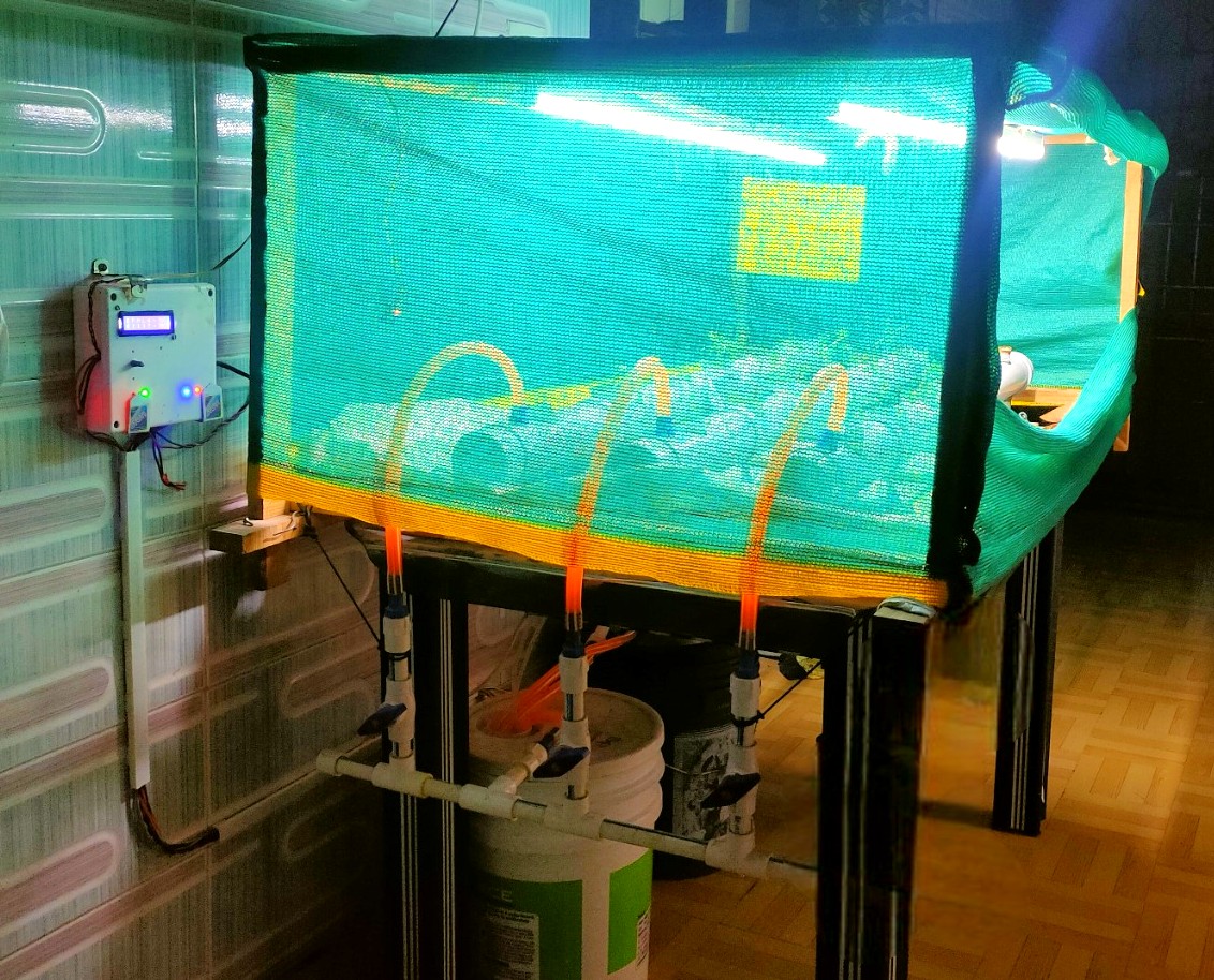
Code released under the MIT License. Docs released under Creative Commons.
| Qty | Value | Footprint | References |
|---|---|---|---|
| 12 | 1k | Resistor_SMD:R_1206_3216Metric | R1, R2, R3, R4, R5, R6, R7, R8, R17, R18, R19, R20 |
| 12 | 5V | Connector_Pin:Pin_D1.0mm_L10.0mm | TP1, TP2, TP3, TP4, TP5, TP6, TP7, TP8, TP15, TP16, TP17, TP18 |
| 6 | 47k | Resistor_SMD:R_1206_3216Metric | R11, R12, R13, R14, R15, R16 |
| 4 | 1N4007 | Diode_THT:D_DO-41_SOD81_P10.16mm_Horizontal | D1, D2, D3, D4 |
| 4 | BC547 | Package_TO_SOT_THT:TO-92L_Wide | Q1, Q2, Q3, Q4 |
| 4 | FINDER-36.11 | Relay_THT:Relay_SPDT_Finder_36.11 | K1, K2, K3, K4 |
| 4 | SFH617A-1 | Package_DIP:DIP-4_W7.62mm | U4, U5, U6, U7 |
| 1 | Arduino_Nano_v3.x | Module:Arduino_Nano | A1 |
| 1 | Bucket_Motor | Connector_Wago:Wago_734-132_1x02_P3.50mm_Vertical | J4 |
| 1 | DHT11 | Connector_JST:JST_EH_B3B-EH-A_1x03_P2.50mm_Vertical | J10 |
| 1 | I2C_LCD | Connector_JST:JST_EH_B4B-EH-A_1x04_P2.50mm_Vertical | J15 |
| 1 | LED_A | Connector_JST:JST_EH_B4B-EH-A_1x04_P2.50mm_Vertical | J11 |
| 1 | LED_K | Connector_JST:JST_EH_B4B-EH-A_1x04_P2.50mm_Vertical | J12 |
| 1 | Lights | Connector_Wago:Wago_734-132_1x02_P3.50mm_Vertical | J5 |
| 1 | Mains_Power | Connector_Wago:Wago_734-132_1x02_P3.50mm_Vertical | J1 |
| 1 | Mist_Motor | Connector_Wago:Wago_734-132_1x02_P3.50mm_Vertical | J3 |
| 1 | Plant_Motor | Connector_Wago:Wago_734-132_1x02_P3.50mm_Vertical | J2 |
| 1 | Sensor_1 | Connector_JST:JST_EH_B4B-EH-A_1x04_P2.50mm_Vertical | J7 |
| 1 | Sensor_2 | Connector_JST:JST_EH_B4B-EH-A_1x04_P2.50mm_Vertical | J6 |
58 parts, built around the DHT11, SFH617A-1 and BC547. The full list of its parts is on this page, with links to each part's symbol and footprint where PCBKit's library has them.
From the bhaskar9980/Guardian repository on GitHub, at the commit this page was made from: the board is PCB_designs/KiCad_PCB_design/Arduino_Relay/Arduino_relay.kicad_pcb. PCBKit opens the board in the browser, with nothing to install.
Its repository publishes it under the MIT licence: you may reuse it on that licence's terms (keep the author's notice, and for a copyleft licence share your changes alike).

janithcbk123/Automated-Greenhouse
Greenhouse Automation Project

Sharan21-cmd/climate-control-pcb-design
A compact and efficient Climate Control PCB designed for monitoring and regulating temperature and humidity using embedded electronics.


Pablo-Ortiz-Lopez/ClimateController
ESP8266 based device which handles the climate of a room.


Febriyandi12/Desain_PCB
Kolaborasi untuk update desain pcb yang telah di research