
2 layers227.8 × 48 mm

 Hackuarium/ion-mobility11
DIY Ion mobility spectrometer
Ampli IMS is an open-source printed circuit board by Hackuarium, from the Hackuarium/ion-mobility repository on GitHub. It is a 2-layer board of 44.4 × 28.5 mm with 15 parts on 9 nets, routed with 59 tracks and 240 vias.
It is built around the LMC6082IM. Its parts include 5 capacitors, 4 connectors, 3 resistors, 2 diodes and 1 IC.
Amplification stage to transform the small current on the target to an acceptable voltage to be read/processed.
Transimpedance circuit with a big gain (10^8) and a voltage follower through a dual precision operationnal amplifier (Texas Instruments LMC6082).
The circuit needs to be as close as possible to the target of the IMS in order to limit the noise present on the signal. One possibility is to solder the PCB directly on the back of the target.
Possible amplification of the noise must be taken into account, and possibly filtered through a very small capacitor (~0.01 pF, thus quite expensive) in the gain stage feedback loop (a bigger resistor amplifies the signal but also the noise).
Below is a picture of the mounted PCB, currently missing the connectors and a potential filtering capacitor C1.
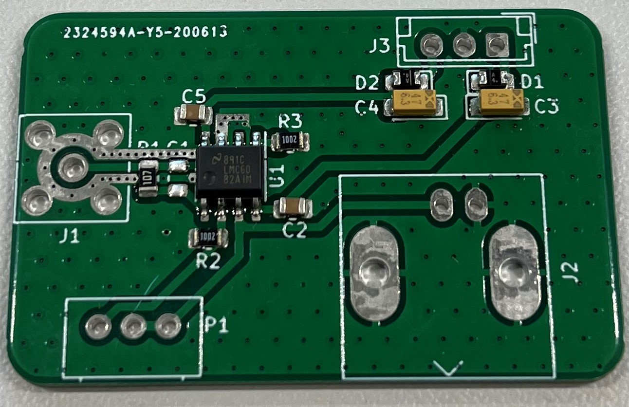
| Qty | Value | Footprint | References |
|---|---|---|---|
| 2 | 0.1uF | Capacitor_SMD:C_0805_2012Metric | C2, C5 |
| 2 | 10K | Capacitor_SMD:C_0805_2012Metric | R2, R3 |
| 2 | 47uF Tant | Capacitor_Tantalum_SMD:CP_EIA-3216-18_Kemet-A_Pad1.58x1.35mm_HandSolder | C3, C4 |
| 2 | D_Schottky | Diode_SMD:D_0805_2012Metric_Castellated | D1, D2 |
| 1 | 0.01pF | Capacitor_SMD:C_0805_2012Metric | C1 |
| 1 | 100M 1/4W | Capacitor_SMD:C_0805_2012Metric | R1 |
| 1 | 300K | Potentiometer_THT:Potentiometer_Alps_RK09Y11_Single_Horizontal | P1 |
| 1 | 5227161-3 | Connector_Coaxial:SMA_Amphenol_132203-12_Horizontal | J1 |
| 1 | 5227161-3 | Connector_Coaxial:BNC_Amphenol_B6252HB-NPP3G-50_Horizontal | J2 |
| 1 | Conn_01x03_Male | Connector_JST:JST_EH_B3B-EH-A_1x03_P2.50mm_Vertical | J3 |
| 1 | LMC6082 | Package_SO:SO-8_3.9x4.9mm_P1.27mm | U1 |


f5bmi/Telemaque
Current, voltage, temperature, forward and reverse signal conditionning before processing by Mentor


GabrielPetrov/hardware-portfolio
Repo containing otherwise offline PCB/Embedded projects

google/mozc-devices
Circuit diagrams and firmware source code for Gboard DIY keyboards

hoglet67/RGBtoHDMI
Bare-metal Raspberry Pi project that provides pixel-perfect sampling of Retro Computer RGB/YUV video and conversion to HDMI

mntmn/amiga2000-gfxcard
MNT VA2000, an Open Source Amiga 2/3/4000 Graphics Card (Zorro II/III), written in Verilog

hackclub/OnBoard
💡 Join 1,000 teenagers and make your first PCB with a $100 grant!

kenp-io/not-for-airpods-repairs
The content of this repository is licensed under the WTFPL License. Please have a close look at the terms before using this material.
It measures 44.4 × 28.5 mm and has 2 copper layers, 1.6 mm thick.
15 parts, built around the LMC6082IM. The full list of its parts is on this page, with links to each part's symbol and footprint where PCBKit's library has them.
From the Hackuarium/ion-mobility repository on GitHub, at the commit this page was made from: the board is PCB/Ampli/Ampli_IMS.kicad_pcb. PCBKit opens the board in the browser, with nothing to install.
Its repository states no licence, so its author keeps all rights: ask Hackuarium before reusing the design.