2 layers
MCP1703-33
Hackuarium/esp-12e
PWM on all the pins ! HSPI (screen or other): 12 13 14 15 PWM: R12 G15 B13 ADC: TOUT I2C: SCL14 SDA2
3 parts

 Hackuarium/esp-12e
PWM on all the pins ! HSPI (screen or other): 12 13 14 15 PWM: R12 G15 B13 ADC: TOUT I2C: SCL14 SDA2
Esp8266 is an open-source printed circuit board by Hackuarium, from the Hackuarium/esp-12e repository on GitHub. It is a 2-layer board of 85 × 75 mm with 62 parts on 47 nets, routed with 439 tracks and 27 vias.
It is built around the ESP-12E, DS18B20 and SI7020-A20-GM, with the DMP1045U among its other parts. Its parts include 18 connectors, 11 resistors, 9 capacitors, 7 ICs and 4 diodes. It belongs with the ESP8266 boards of this library.


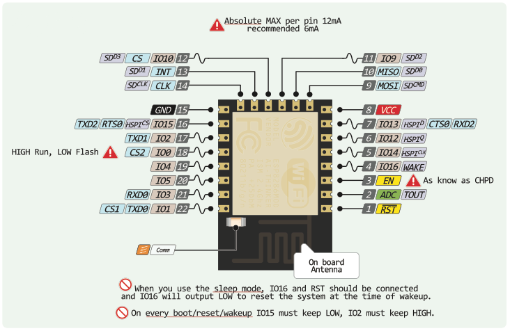
| GPIO | Arduino | ||||||
|---|---|---|---|---|---|---|---|
| 0 | SPI_CS2 | HIGH: normal, LOW: programming | LOW / HIGH | D3 | button LOW / BLK | ||
| 1 | SPI_CS1 | U0_TXD | TX | D10 | TX | ||
| 2 | U1_TXD | on boot HIGH for programming | HIGH | D4 | One WIRE (HIGH) | ||
| 3 | U0_RXD | RX | D9 | RX | |||
| 4 | I2C | D2/SDA | SDA | ||||
| 5 | I2C | D1/SCL | SCL | ||||
| 6 | SDIO_CLK | SPI_CLK | used to connect flash 4MB | reserved | |||
| 7 | SDIO_DATA0 | SPI_MISO | used to connect flash 4MB | reserved | |||
| 8 | SDIO_DATA1 | SPI_MOSI | U1_RXD | used to connect flash 4MB | reserved | ||
| 9 | SDIO_DATA2 | SPI_HD | HSPI_HD | used to connect flash 4MB | reserved | ||
| 10 | SDIO_DATA3 | SPI_WP | HSPI_WP | used to connect flash 4MB | reserved | ||
| 11 | SDIO_CMD | SPI_CS0 | used to connect flash 4MB | reserved | |||
| 12 | MTDI | HSPI_MISO | MISO | D6 | PWM R | ||
| 13 | MTCK | HSPI_MOSI | U0_CTS | MOSI | D7 | PWM G | |
| 14 | MTMS | HSPI_CLK | CLK | D5 | PWM B | ||
| 15 | MTDO | HSPI_CS | U0_RTS | on boot LOW for programming | LOW / CS | D8 | PWM W (LOW) |
| 16 | XPD_DCDC | sleep mode to EXT_RSTB (allow deep sleep) | RESET | D0 | RST | ||
| 17 | ADC | voltage 0—1.0V | Battery | A0 | |||
| RESET | Pull UP |
15: WS2812, adressable led
Read information on: https://www.kloppenborg.net/images/blog/esp8266/esp8266-esp12e-specs.pdf
Available pins: http://www.rabbithacks.com/esp8266/esp12-e-directly-usable-gpio-pins/
PWM on all the pins ! HSPI (screen or other): 12 13 14 15 PWM: R12 G15 B13 ADC: TOUT I2C: SCL14 SDA2
You need to maintain SW2 while pressing SW1 (reset) in order to set the ESP-12E in programing mode.
https://randomnerdtutorials.com/esp8266-and-node-red-with-mqtt/
With SSL (secure)? :
https://hackaday.io/project/163666-secure-esp8266-mqtt-poc/log/158992-secure-mqtt-broker-setup
It seems impossible to program the ESP-12E with RTOS from the Arduino IDE.
The SDK is maintained by Expressif and it svailable on:
https://github.com/espressif/ESP8266_RTOS_SDK
You will also find on this page the instructions to install the SDK
| Qty | Value | Footprint | References |
|---|---|---|---|
| 7 | 10k | Resistor_SMD:R_0805_2012Metric_Pad1.15x1.40mm_HandSolder | R2, R3, R4, R7, R8, R10, R11 |
| 4 | 10uF | Capacitor_SMD:C_0805_2012Metric_Pad1.15x1.40mm_HandSolder | C1, C2, C8, C9 |
| 4 | 1uF | Capacitor_SMD:C_0805_2012Metric_Pad1.15x1.40mm_HandSolder | C4, C5, C6, C7 |
| 4 | BSP75 | Package_TO_SOT_SMD:SOT-223 | Q1, Q2, Q3, Q4 |
| 4 | hole | MountingHole:MountingHole_3.2mm_M3 | J15, J16, J17, J18 |
| 3 | D_Schottky | Diode_SMD:D_SOD-123 | D1, D3, D4 |
| 2 | Onewire | Connector_Audio:Jack_3.5mm_Ledino_KB3SPRS_Horizontal | J6, J7 |
| 2 | RJ12-I2C | Connector_RJ:RJ12_Amphenol_54601 | J4, J5 |
| 1 | +12V | Connector_Wire:SolderWirePad_1x01_SMD_5x10mm | J14 |
| 1 | 100k | Resistor_SMD:R_0805_2012Metric_Pad1.15x1.40mm_HandSolder | R1 |
| 1 | 100nF | Capacitor_SMD:C_0805_2012Metric_Pad1.15x1.40mm_HandSolder | C3 |
| 1 | 1M | Resistor_SMD:R_0805_2012Metric_Pad1.15x1.40mm_HandSolder | R5 |
| 1 | 270k | Resistor_SMD:R_0805_2012Metric_Pad1.15x1.40mm_HandSolder | R6 |
| 1 | 3.3V | TestPoint:TestPoint_2Pads_Pitch2.54mm_Drill0.8mm | TP6 |
| 1 | 4.7k | Resistor_SMD:R_0805_2012Metric_Pad1.15x1.40mm_HandSolder | R9 |
| 1 | 5 / 12V | Connector_BarrelJack:BarrelJack_Horizontal | J2 |
| 1 | 5V | TestPoint:TestPoint_2Pads_Pitch2.54mm_Drill0.8mm | TP1 |
| 1 | BATT | Connector_Molex:Molex_KK-254_AE-6410-02A_1x02_P2.54mm_Vertical | J1 |
| 1 | Blue | Connector_Wire:SolderWirePad_1x01_SMD_5x10mm | J11 |
| 1 | CONN FT232RL | Connector_PinHeader_2.54mm:PinHeader_1x06_P2.54mm_Vertical | J3 |
| 1 | DMP1045U | Package_TO_SOT_SMD:SOT-23 | D2 |
| 1 | DS18B20 | Package_TO_SOT_THT:TO-92_Inline | U7 |
| 1 | ESP-12E | RF_Module:ESP-12E | U1 |
| 1 | Green | Connector_Wire:SolderWirePad_1x01_SMD_5x10mm | J10 |
| 1 | IO_RGBW | Connector_PinHeader_2.54mm:PinHeader_1x08_P2.54mm_Vertical | J13 |
| 1 | MCP1703-33 | Package_TO_SOT_SMD:SOT-23 | U3 |
| 1 | MCP1703-50 | Package_TO_SOT_SMD:SOT-23 | U5 |
| 1 | MCP73831-2 | Package_TO_SOT_SMD:SOT-23-5 | U2 |
| 1 | MS5637 | hackuarium:MS5637 | U4 |
| 1 | OneWire | TestPoint:TestPoint_2Pads_Pitch2.54mm_Drill0.8mm | TP3 |
| 1 | PROG | Button_Switch_SMD:SW_SPST_PTS645 | SW2 |
| 1 | Pad | Connector_Wire:SolderWirePad_1x01_SMD_5x10mm | J9 |
| 1 | RESET | Button_Switch_SMD:SW_SPST_PTS645 | SW1 |
| 1 | Red | Connector_Wire:SolderWirePad_1x01_SMD_5x10mm | J8 |
| 1 | Si7020-A20 | Package_DFN_QFN:DFN-6-1EP_3x3mm_P1mm_EP1.5x2.4mm | U6 |
| 1 | Test_UART | Connector_PinHeader_2.54mm:PinHeader_1x03_P2.54mm_Vertical | TP7 |
| 1 | Test_i2C | Connector_PinHeader_2.54mm:PinHeader_1x03_P2.54mm_Vertical | TP2 |
| 1 | V_BAT | TestPoint:TestPoint_2Pads_Pitch2.54mm_Drill0.8mm | TP4 |
| 1 | V_OUT | TestPoint:TestPoint_2Pads_Pitch2.54mm_Drill0.8mm | TP5 |
| 1 | White | Connector_Wire:SolderWirePad_1x01_SMD_5x10mm | J12 |
It measures 85 × 75 mm and has 2 copper layers, 1.6 mm thick.
62 parts, built around the ESP-12E, DS18B20, SI7020-A20-GM and DMP1045U. The full list of its parts is on this page, with links to each part's symbol and footprint where PCBKit's library has them.
From the Hackuarium/esp-12e repository on GitHub, at the commit this page was made from: the board is kicad/esp8266.kicad_pcb. PCBKit opens the board in the browser, with nothing to install.
Its repository states no licence, so its author keeps all rights: ask Hackuarium before reusing the design.
Hackuarium/esp-12e
PWM on all the pins ! HSPI (screen or other): 12 13 14 15 PWM: R12 G15 B13 ADC: TOUT I2C: SCL14 SDA2

Hackuarium/esp-32wroom
Start by installing the ESP32 board in Arduino IDE https://randomnerdtutorials.com/installing-the-esp32-board-in-arduino-ide-mac-and-linux-instructions/ (Mac/Linux)…

XasWorks/dragon-home
A rework of our old SmartHome project, this time done cleanly and neatly~

pluggee/piweather
raspberry pi based system for weather monitoring and automation

jainamnahar14surat/Flight-Computer
A compact, custom-designed PCB (Printed Circuit Board) for a Flight Computer, aimed at aerospace applications like model rockets, UAVs, and experimental aircrafts.

juniper-garden/twig_temp_humidity_sensor
Hardware files for the temperature and humidity sensor

kajusK/Picoballoon2020
Probe for Observatory and Planetarium Brno Picoballoon Challenge 2020

UtilitechAS/amsreader-firmware
ESP8266 and ESP32 compatible firmware to read, interpret and publish data to MQTT from smart electrical meters, both DLMS and DSMR is supported

AnaviTechnology/anavi-thermometer
WiFi Smart Thermometer with ESP8266, DHT22, DS18B20, OLED display and slots for up to 3 I2C sensor modules