2 layers85 × 75 mm
Esp8266
Hackuarium/esp-12e
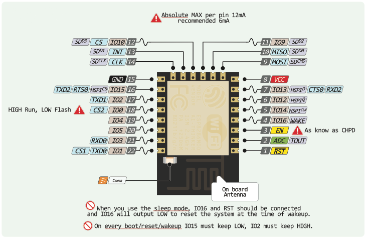
PWM on all the pins ! HSPI (screen or other): 12 13 14 15 PWM: R12 G15 B13 ADC: TOUT I2C: SCL14 SDA2
62 parts

 Hackuarium/esp-12e
PWM on all the pins ! HSPI (screen or other): 12 13 14 15 PWM: R12 G15 B13 ADC: TOUT I2C: SCL14 SDA2
MCP1703-33 is an open-source printed circuit board by Hackuarium, from the Hackuarium/esp-12e repository on GitHub. It is a 2-layer board with 3 parts on 3 nets, routed with 8 tracks and 0 vias.
Its parts include 2 capacitors and 1 IC.
| GPIO | Arduino | ||||||
|---|---|---|---|---|---|---|---|
| 0 | SPI_CS2 | HIGH: normal, LOW: programming | LOW / HIGH | D3 | button LOW / BLK | ||
| 1 | SPI_CS1 | U0_TXD | TX | D10 | TX | ||
| 2 | U1_TXD | on boot HIGH for programming | HIGH | D4 | One WIRE (HIGH) | ||
| 3 | U0_RXD | RX | D9 | RX | |||
| 4 | I2C | D2/SDA | SDA | ||||
| 5 | I2C | D1/SCL | SCL | ||||
| 6 | SDIO_CLK | SPI_CLK | used to connect flash 4MB | reserved | |||
| 7 | SDIO_DATA0 | SPI_MISO | used to connect flash 4MB | reserved | |||
| 8 | SDIO_DATA1 | SPI_MOSI | U1_RXD | used to connect flash 4MB | reserved | ||
| 9 | SDIO_DATA2 | SPI_HD | HSPI_HD | used to connect flash 4MB | reserved | ||
| 10 | SDIO_DATA3 | SPI_WP | HSPI_WP | used to connect flash 4MB | reserved | ||
| 11 | SDIO_CMD | SPI_CS0 | used to connect flash 4MB | reserved | |||
| 12 | MTDI | HSPI_MISO | MISO | D6 | PWM R | ||
| 13 | MTCK | HSPI_MOSI | U0_CTS | MOSI | D7 | PWM G | |
| 14 | MTMS | HSPI_CLK | CLK | D5 | PWM B | ||
| 15 | MTDO | HSPI_CS | U0_RTS | on boot LOW for programming | LOW / CS | D8 | PWM W (LOW) |
| 16 | XPD_DCDC | sleep mode to EXT_RSTB (allow deep sleep) | RESET | D0 | RST | ||
| 17 | ADC | voltage 0—1.0V | Battery | A0 | |||
| RESET | Pull UP |
15: WS2812, adressable led
Read information on: https://www.kloppenborg.net/images/blog/esp8266/esp8266-esp12e-specs.pdf
Available pins: http://www.rabbithacks.com/esp8266/esp12-e-directly-usable-gpio-pins/
PWM on all the pins ! HSPI (screen or other): 12 13 14 15 PWM: R12 G15 B13 ADC: TOUT I2C: SCL14 SDA2
You need to maintain SW2 while pressing SW1 (reset) in order to set the ESP-12E in programing mode.
https://randomnerdtutorials.com/esp8266-and-node-red-with-mqtt/
With SSL (secure)? :
https://hackaday.io/project/163666-secure-esp8266-mqtt-poc/log/158992-secure-mqtt-broker-setup
It seems impossible to program the ESP-12E with RTOS from the Arduino IDE.
The SDK is maintained by Expressif and it svailable on:
https://github.com/espressif/ESP8266_RTOS_SDK
You will also find on this page the instructions to install the SDK
| Qty | Value | Footprint | References |
|---|---|---|---|
| 2 | 1uF | Capacitor_SMD:C_0805_2012Metric_Pad1.15x1.40mm_HandSolder | C1, C2 |
| 1 | MCP1703A-3302_SOT23 | Package_TO_SOT_SMD:SOT-23 | U1 |
Hackuarium/esp-12e
PWM on all the pins ! HSPI (screen or other): 12 13 14 15 PWM: R12 G15 B13 ADC: TOUT I2C: SCL14 SDA2


hzeller/rpi-rgb-led-matrix
Controlling up to three chains of 64x64, 32x32, 16x32 or similar RGB LED displays using Raspberry Pi GPIO


atopile/atopile
Design circuit boards with code! ✨ Get software-like design reuse 🚀, validation, version control and collaboration in hardware; starting with electronics ⚡️


hackclub/sprig
🍃 Learn to code by making games in a JavaScript web-based game editor.
3 parts. The full list of its parts is on this page, with links to each part's symbol and footprint where PCBKit's library has them.
From the Hackuarium/esp-12e repository on GitHub, at the commit this page was made from: the board is kicad/schemas/MCP1703-33.kicad_pcb. PCBKit opens the board in the browser, with nothing to install.
Its repository states no licence, so its author keeps all rights: ask Hackuarium before reusing the design.