4 layers96 × 70 mm
Tradewind
binaryBeachLLC/tradewind
Tradewind TW-1: solar LoRaWAN field sensor. KiCad 9 board, CadQuery enclosure, RUI3 firmware, simulations, test data, report and datasheet.
85 parts

 h0lad/LoRaHarvesterBox11
PCB integrating a ST STM32WLE5CC and TI BQ25570 energy harvester. Ideal platform for ultra-low-power LoRa(WAN) nodes projects.
LoRaHarvesterBox is an open-source printed circuit board by h0lad, from the h0lad/LoRaHarvesterBox repository on GitHub, published under the CERN-OHL-S-2.0 licence. It is a 4-layer board of 48 × 45.5 mm with 46 parts on 47 nets, routed with 343 tracks and 202 vias.
It is built around the RAK3172-8-SM-I, TPS22917DBV and SSSS811101, with the TS-1088-AR02016 among its other parts. Its parts include 10 capacitors, 9 resistors, 9 connectors, 4 ICs and 2 switches. It belongs with the radio and wireless boards and the STM32 boards of this library.


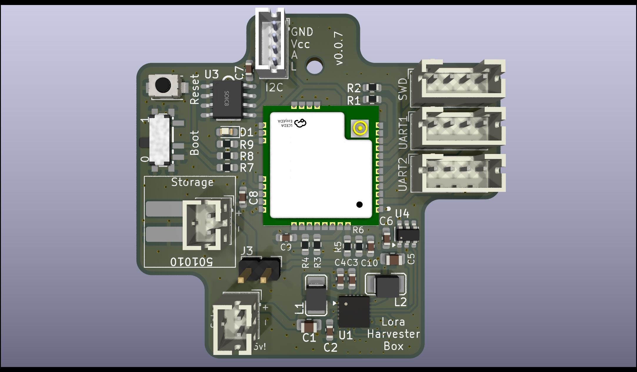
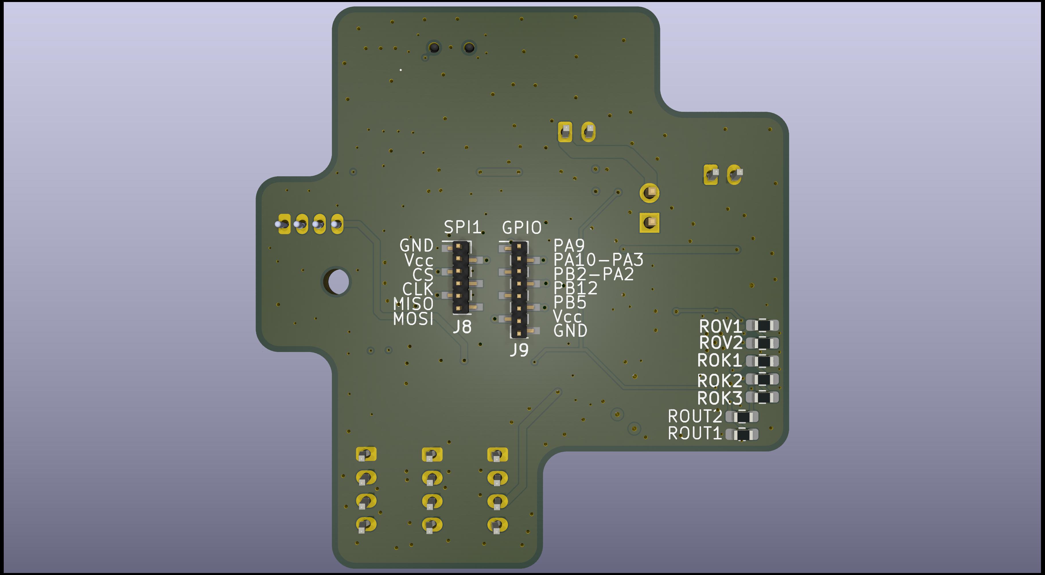
This generic LoRa base board is built around the ST STM32WLE5CC (RAK3172) and the TI BQ25570 energy harvester.
It is suitable for a wide range of applications, including:
For persistent data storage, an optional FRAM IC (Infineon FM24V10) can be added using I²C. A variety of sensors can additonaly integrated through I²C, SPI (on the back), or USART interfaces.
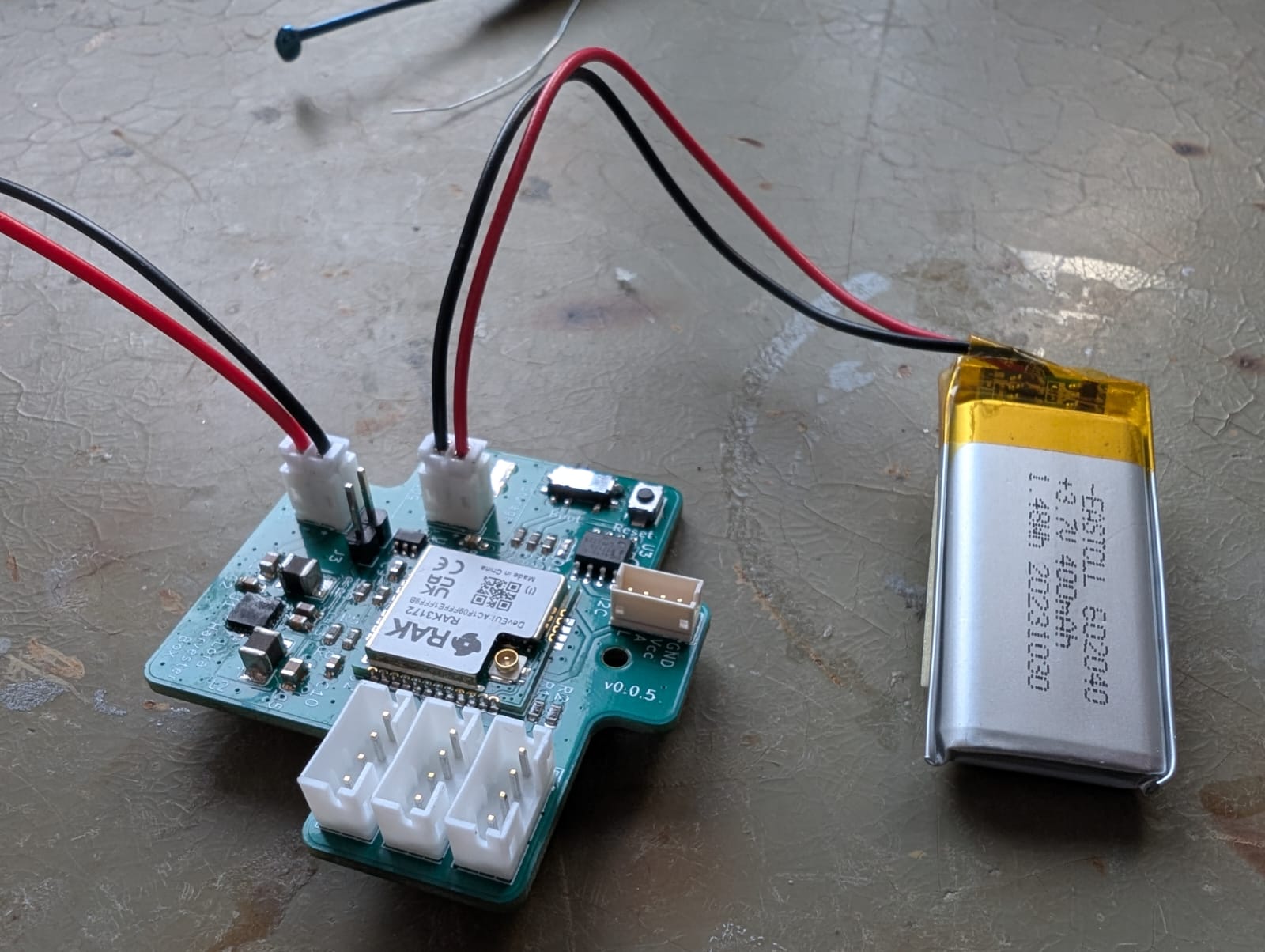
The power supply design is highly flexible: alongside standard JST-PH connectors, the board also supports very small LiPo batteries (commonly used in in-ear headphones or Bluetooth headsets), which can be soldered directly. Such batteries are readily available on AliExpress (e.g. 501010). The TI BQ25570 also supports exotic storages like Supercaps, LTO, etc.
Uses the standardized RAK housing which can house a variety of platforms (ESP32, STM32, etc.) with compatible pins. This variant uses the RAK3172 (ST STM32WLE5CC: 256Kb Flash, 64Kb RAM, 48MHz).
Exposed interfaces:
Uses the Semtech SX1262 integrated within the STM32 housing. Multiple RAK variants available for 433/470/868/915MHz.
Infineon FM24V10: 1-MBit non-volatile F-RAM for storing firmware updates, messages or mesurement data
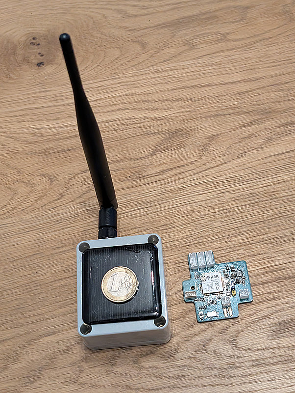
This weirdo PCB format is designed around the cheapest water protected box from Aliexpress.
It's the only energy harvester that supports up to 110mA peak current.
I'm not overly happy with this IC as it lacks a few useful features:
No I²C interface and ADC for reading voltages/currents
No Thermistor for switching off charging above and below specific temperatures
Doesn't switch off VOUT if the battery hits the lower threshold. It only signals it using a pin.
Rather annoying pin configuration. Layouting it doesn't make much fun.
It doesn't have interal high-precision resistors for configuring the voltage limits (VBAT_OV, etc.). Even with 1% tolerance resistors the resulting voltage ranges are barely acceptable due to error propagation.
Lowest possible battery voltage is 1.9V. This means we cannot utilize the full capacity of "exotic" storage types like LTO- and NaIon-cells.
Honestly - It's an old thing compared to the latest generation from ST or e-peas.
Using a SoC module from RAK brings all the HF and impedancy matching.
Everything else leaving the housing is not really critical signal wise.
Also it's not too expensive with 6€.
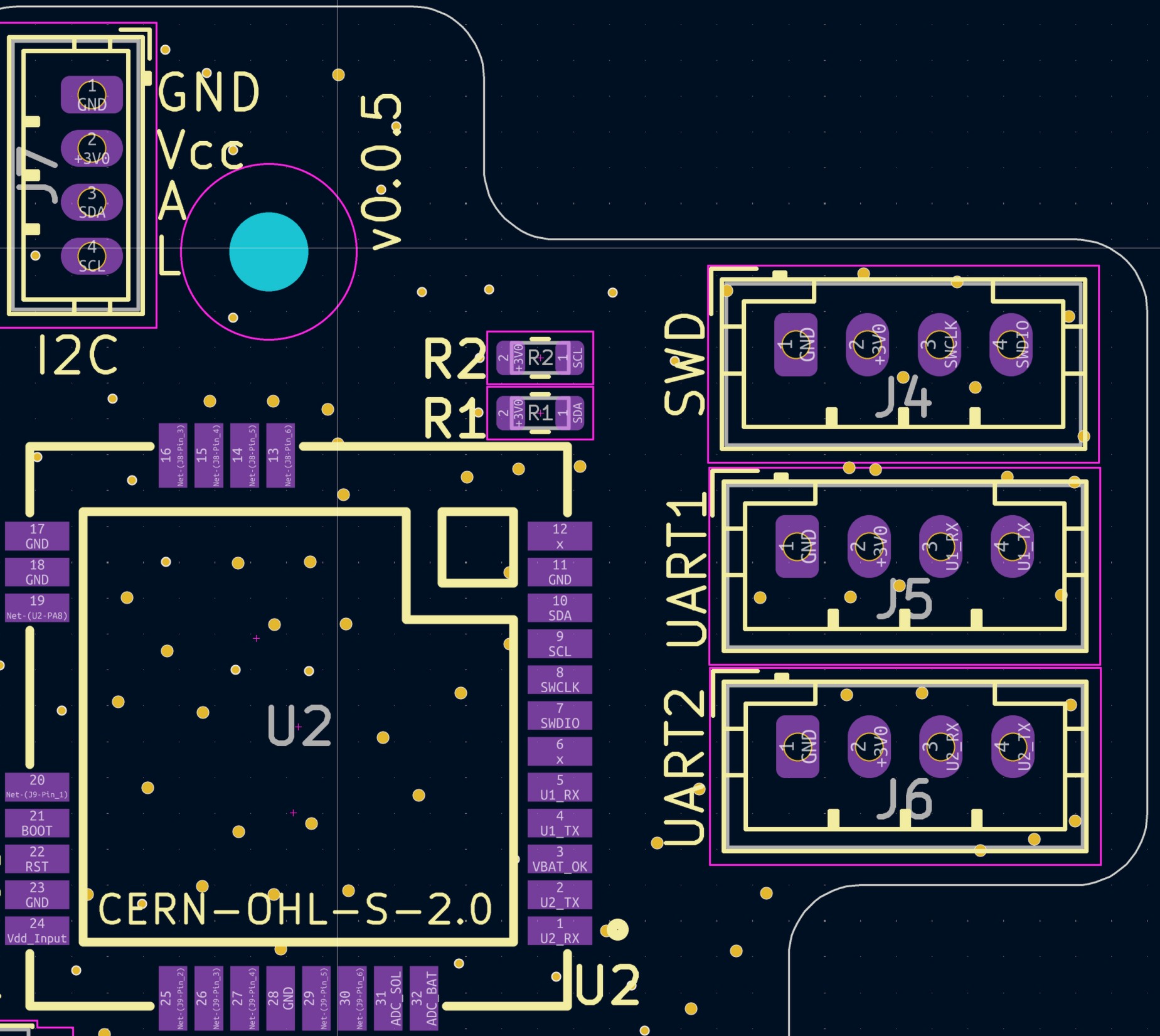
| Signal | Pin | ADC Channel | Info |
|---|---|---|---|
| Energy Storage Voltage | PB3 | A0 | Voltage goes through a Voltage Divider |
| Energy Source Voltage | PB4 | A1 | Voltage goes through a Voltage Divider |
| Peripheral | TX Pin | RX Pin |
|---|---|---|
| UART1 | PB6 | PB7 |
| UART2 | PA2 | PA3 |
| Signal | Pin |
|---|---|
| SWDIO | PA13 |
| SWCLK | PA14 |
| Signal | Pin |
|---|---|
| SPI1, MOSI | PA7 |
| SPI1, MISO | PA6 |
| SPI1, CLK | PA5 |
| SPI1, NSS | PA4 |
| Signal | Pin |
|---|---|
| LED | PA8 |
| Signal | Pin |
|---|---|
| VBAT_OK from TI BQ25570 | PA15 |
Warning:
You have to be super careful here. Don't trust your 1%-SMD-Resistor book from Aliexpress or Amazon. Measure each resistor with a high-resolution multimeter and then calculate the voltages according to the readings! A shabby Libreoffice Calc sheet can be found within the docs folder to do this.
I wrote a script for calculating resistor values here: ti-bq25570-calculator.
Power Chain
✅ 3.3V from TI BQ25570
✅ Charges power storage as defined with R_OV1 and R_OV2
✅ VBAT_OK signal with 3.3V LiPo attached as a storage
✅ Boosts 0.6V to 3.3V without energy storage attached
✅ Lower and upper VBAT_OK threshold
✅ Power switch (TI TPS22917DBV)
ST STM32WL55
✅ Connect to the SWD interface using a ST-Link
Findings
The BQ25570 doesn't like my extremely noisy power supply as a storage emulation. It doesn't come up.
You have to be very careful as even the tolerance of 1% resistors (R_OV1 and R_OV2) might cause overcharging. So stay away from the hard limits of your battery.
CERN Open Hardware Licence Version 2 - Strongly Reciprocal
| Qty | Value | Footprint | References |
|---|---|---|---|
| 4 | 100nF | Capacitor_SMD:C_0603_1608Metric_Pad1.08x0.95mm_HandSolder | C7, C8, C9, C10 |
| 4 | 500k | Resistor_SMD:R_0603_1608Metric_Pad0.98x0.95mm_HandSolder | R3, R4, R5, R6 |
| 3 | Conn_01x04_Socket | Connector_JST:JST_PH_B4B-PH-K_1x04_P2.00mm_Vertical | J4, J5, J6 |
| 2 | 10k | Resistor_SMD:R_0603_1608Metric | R1, R2 |
| 2 | 10nF | Capacitor_SMD:C_0603_1608Metric_Pad1.08x0.95mm_HandSolder | C2, C3 |
| 2 | 5.1M | Resistor_SMD:R_0603_1608Metric_Pad0.98x0.95mm_HandSolder | ROUT1, ROV2 |
| 2 | Conn_01x02_Pin | Connector_JST:JST_PH_B2B-PH-K_1x02_P2.00mm_Vertical | J1, J2 |
| 1 | 1.9M | Resistor_SMD:R_0603_1608Metric_Pad0.98x0.95mm_HandSolder | ROK3 |
| 1 | 100 | Resistor_SMD:R_0603_1608Metric_Pad0.98x0.95mm_HandSolder | R8 |
| 1 | 10k | Resistor_SMD:R_0603_1608Metric_Pad0.98x0.95mm_HandSolder | R7 |
| 1 | 10uF | Capacitor_SMD:C_0805_2012Metric_Pad1.18x1.45mm_HandSolder | C5 |
| 1 | 10uH | SolarMeshRepeater_Lib:L1210 | L2 |
| 1 | 1uF | Capacitor_SMD:C_0603_1608Metric_Pad1.08x0.95mm_HandSolder | C6 |
| 1 | 22uH | SolarMeshRepeater_Lib:L1210 | L1 |
| 1 | 3.9M | Resistor_SMD:R_0603_1608Metric_Pad0.98x0.95mm_HandSolder | ROV1 |
| 1 | 330 | Resistor_SMD:R_0603_1608Metric_Pad0.98x0.95mm_HandSolder | R9 |
| 1 | 4.3M | Resistor_SMD:R_0603_1608Metric_Pad0.98x0.95mm_HandSolder | ROK1 |
| 1 | 4.7uF | Capacitor_SMD:C_0603_1608Metric_Pad1.08x0.95mm_HandSolder | C4 |
| 1 | 4.7uF | Capacitor_SMD:C_0805_2012Metric_Pad1.18x1.45mm_HandSolder | C1 |
| 1 | 6.8M | Resistor_SMD:R_0603_1608Metric_Pad0.98x0.95mm_HandSolder | ROK2 |
| 1 | 7.5M | Resistor_SMD:R_0603_1608Metric_Pad0.98x0.95mm_HandSolder | ROUT2 |
| 1 | BQ25570 | Package_DFN_QFN:QFN-20-1EP_3.5x3.5mm_P0.5mm_EP2x2mm | U1 |
| 1 | Battery | SolarMeshRepeater_Lib:501010 | BT1 |
| 1 | Conn_01x02_Pin | Connector_PinHeader_2.54mm:PinHeader_1x02_P2.54mm_Vertical | J3 |
| 1 | Conn_01x04_Socket | Connector_JST:JST_ZH_B4B-ZR_1x04_P1.50mm_Vertical | J7 |
| 1 | Conn_01x06_Socket | Connector_PinHeader_1.00mm:PinHeader_1x06_P1.00mm_Vertical_SMD_Pin1Left | J8 |
| 1 | Conn_01x08_Socket | Connector_PinHeader_1.00mm:PinHeader_1x08_P1.00mm_Vertical_SMD_Pin1Left | J9 |
| 1 | FM24V10-GTR_C466851 | SolarMeshRepeater_Lib:SOIC-8_L5.0-W4.0-P1.27-LS6.0-BL | U3 |
| 1 | LED | LED_SMD:LED_0603_1608Metric_Pad1.05x0.95mm_HandSolder | D1 |
| 1 | MountingHole | MountingHole:MountingHole_2.2mm_M2 | H1 |
| 1 | RAK3172-8-SM-I | SolarMeshRepeater_Lib:WIRELM-SMD_32P-L15.5-W15.0-P1.00 | U2 |
| 1 | SSSS811101 | SolarMeshRepeater_Lib:SW-SMD_SSSS811101 | SW1 |
| 1 | TPS22917DBV | Package_TO_SOT_SMD:SOT-23-6 | U4 |
| 1 | TS-1088-AR02016 | SolarMeshRepeater_Lib:SW-SMD_L3.9-W3.0-P4.45 | SW2 |
binaryBeachLLC/tradewind
Tradewind TW-1: solar LoRaWAN field sensor. KiCad 9 board, CadQuery enclosure, RUI3 firmware, simulations, test data, report and datasheet.

piecol/CM5_MINIMA_REV1
CM5 LoRaWAN carrier board in a compact, feature-filled footprint

h0lad/SolarMeshtasticNode
This is a Meshtastic Solar Node PCB based on the Heltec HT-CT62 and the linear solar charge controller TI BQ25185.


h0lad/LoRaPowerBox
The LoRaPowerBox combines the Heltec HT-CT62 module (ESP32C3 + Semtech SX1262) with a TI BQ25628E wide-range charger. Main target is IoT projects that deliver data over LoRa and/or Wifi utilizing solar power.

tangles-0/cyberdeck-scout
// #ifndef PINPA0 // #define PINPA0 11 // #endif // #ifndef PINPA1 // #define PINPA1 8 // #endif // #ifndef PINPA2 // #define PINPA2 9 // #endif // #ifndef PINPA3 // #define PINPA3 10 // #endif // #ifndef PINPA4 //…

It measures 48 × 45.5 mm and has 4 copper layers, 1.6 mm thick.
46 parts, built around the RAK3172-8-SM-I, TPS22917DBV, SSSS811101 and TS-1088-AR02016. The full list of its parts is on this page, with links to each part's symbol and footprint where PCBKit's library has them.
From the h0lad/LoRaHarvesterBox repository on GitHub, at the commit this page was made from: the board is pcb/LoraHarvesterBox.kicad_pcb and its schematic pcb/LoraHarvesterBox.kicad_sch. PCBKit opens the board in the browser, with nothing to install.
Its repository publishes it under the CERN-OHL-S-2.0 licence: you may reuse it on that licence's terms (keep the author's notice, and for a copyleft licence share your changes alike).