8 layers
Round pendant
sequoia-hope/ultraroute
PCB autorouting experiments around copperroute: route jobs, leaderboards, board morphing
342 parts1MIT

 gsteiert/CycloMod20
Cyclone 10LP MicroMod Processor Board
CycloMod is an open-source printed circuit board by gsteiert, from the gsteiert/CycloMod repository on GitHub, published under the CC0-1.0 licence. It is a 4-layer board of 22 × 22 mm with 72 parts on 130 nets, routed with 1,317 tracks and 174 vias.
It is built around the 10CL016YM164I7G, RP2350A and W25Q128JVPIQ, with the XC6233H2519R-G, IN-S42BT5B and CC0201JRNPO9BN150 among its other parts. Its parts include 38 capacitors, 15 resistors, 5 ICs, 3 diodes and 1 connector. It belongs with the RP2350 boards of this library.


Cyclone 10LP plus RP2350 in SparkFun MicroMod form-factor
Be sure to subscribe to the Cyclomod Crowd Supply Campaign for updates on when and how to get CycloMod.
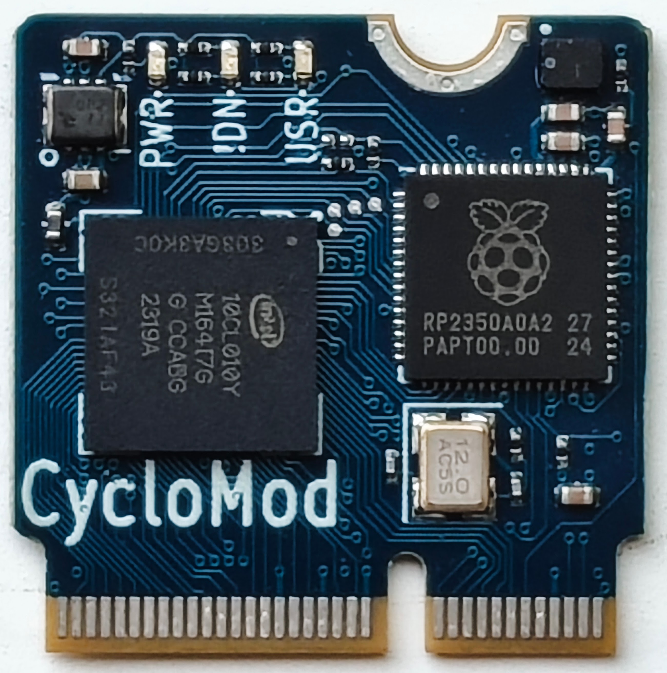
CycloMod brings the flexibility of an FPGA to the SparkFun MicroMod ecosystem. It combines the Raspberry Pi RP2350 with the Altera Cyclone 10LP, in a compact, adaptable module.
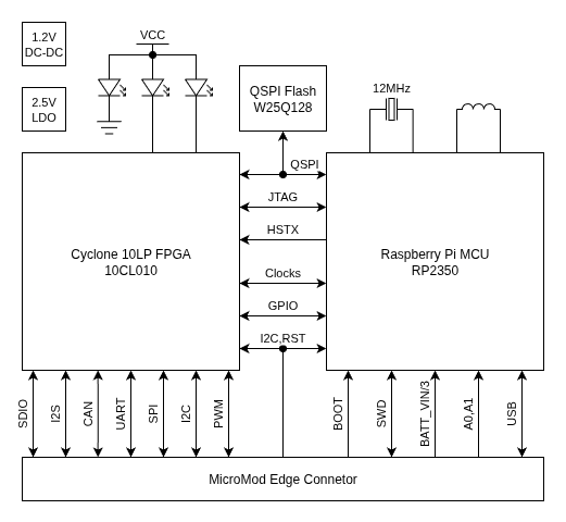
The FPGA and MCU are designed to be used together. Most of the MicroMod I/O are connected to the FPGA for highest flexibility, while some functions like USB, ADC and SWD take advantage of the dedicated peripherals in the RP2350. A few signals, like reset and the primary I2C bus, are connected to both devices.
Most of the RP2350 I/O are connected to Cyclone 10LP. The MCU is connected to the JTAG pins of the FPGA so that the same flash can store the MCU firmware and FPGA images to be loaded with the Altera JBC player. GPIO on the FPGA are connected to the MCU QSPI interface to provide a reasonable speed data path between the two devices. The HSTX port is also connected for higher speed streaming from the MCU to the FPGA. Input and Output clocks are also connected between the two devices to allow for sharing the 12MHz refernce crystal from the MCU and PLLs in the FPGA.
The primary intended use case is for the RP2350 to manage the loading of the FPGA to eliminate the need for an additional storage device. The active serial configuration pins are connected to the SPI port pins on the MicroMod card edge and there is a solder bridge selector that can be cut and shorted to enable laoding the FPGA from external SPI flash.
FPGA images can be transfered to flash over USB using the UF2 flash loader built into the RP2350 ROM. Altera provides a JAM Byte Code player that can be used to load the FPGA over JTAG. A script is available to combine the JBC file with the RP2350 firmware in a single UF2 file. This methodology was demonstrated in the "Build a $5 FPGA loader" workshop at Crowd Supply Teardown 2024.
| Qty | Value | Footprint | References |
|---|---|---|---|
| 22 | 100n | Capacitor_SMD:C_0201_0603Metric | C3, C10, C11, C12, C13, C14, C15, C18, C21, C22, C23, C24, C25, C26, C27, C28 +6 |
| 6 | 10k | Resistor_SMD:R_0201_0603Metric | R2, R3, R4, R9, R11, R15 |
| 6 | 4.7u | Capacitor_SMD:C_0402_1005Metric | C4, C8, C19, C20, C32, C38 |
| 5 | 1k | Resistor_SMD:R_0201_0603Metric | R1, R7, R8, R10, R14 |
| 5 | 1u | Capacitor_SMD:C_0402_1005Metric | C6, C7, C9, C29, C33 |
| 3 | LED | LED_SMD:LED_0402_1005Metric | D1, D2, D3 |
| 2 | 15p | Capacitor_SMD:C_0201_0603Metric | C1, C2 |
| 2 | 27 | Resistor_SMD:R_0201_0603Metric | R12, R13 |
| 2 | 4.7u | custom:C_0402_1005Metric_small_pads | C16, C17 |
| 1 | 1.2V | custom:CL-2025-02 | U3 |
| 1 | 10CL016YM164 | custom:M164_8.0x8.0mm_0.5mm | U1 |
| 1 | 10u | Capacitor_SMD:C_0402_1005Metric | C5 |
| 1 | 120 | Resistor_SMD:R_0402_1005Metric | FB1 |
| 1 | 3.3u | custom:L_pol_2016 | L1 |
| 1 | 33 | Resistor_SMD:R_0201_0603Metric | R6 |
| 1 | ABM8-272-T3 | Crystal:Crystal_SMD_3225-4Pin_3.2x2.5mm | Y1 |
| 1 | DNF | Resistor_SMD:R_0201_0603Metric | R5 |
| 1 | FRAME-LEDGER | MicroMod-RP2040-ProcessorBoard:CREATIVE_COMMONS | FRAME1 |
| 1 | MICROMOD-2222 | custom:MicroMod_Processor | J1 |
| 1 | OSHW-LOGOMINI | MicroMod-RP2040-ProcessorBoard:OSHW-LOGO-MINI | LOGO3 |
| 1 | RP2350_60QFN | custom:RP2350-QFN-60-1EP_7x7_P0.4mm_EP3.4x3.4mm_ThermalVias | U4 |
| 1 | SolderJumper_3_Bridged12 | custom:SolderJumper-3pin_Bridged_RoundedPad_0402 | JP2 |
| 1 | TCK | custom:TestPoint_Pad_D0.5mm | TP2 |
| 1 | TDI | custom:TestPoint_Pad_D0.5mm | TP1 |
| 1 | TDO | custom:TestPoint_Pad_D0.5mm | TP4 |
| 1 | TMS | custom:TestPoint_Pad_D0.5mm | TP3 |
| 1 | W25Q128JVP | Package_SON:WSON-8-1EP_6x5mm_P1.27mm_EP3.4x4.3mm | U2 |
| 1 | XC6223-2.5V | Package_DFN_QFN:UDFN-4-1EP_1x1mm_P0.65mm_EP0.48x0.48mm | U5 |
It measures 22 × 22 mm and has 4 copper layers, 1.6 mm thick.
72 parts, built around the 10CL016YM164I7G, RP2350A, W25Q128JVPIQ and XC6233H2519R-G. The full list of its parts is on this page, with links to each part's symbol and footprint where PCBKit's library has them.
From the gsteiert/CycloMod repository on GitHub, at the commit this page was made from: the board is CycloMod.kicad_pcb and its schematic CycloMod.kicad_sch. PCBKit opens the board in the browser, with nothing to install.
Its repository publishes it under the CC0-1.0 licence: you may reuse it on that licence's terms (keep the author's notice, and for a copyleft licence share your changes alike).
sequoia-hope/ultraroute
PCB autorouting experiments around copperroute: route jobs, leaderboards, board morphing


Cybdo/CybdoDuino
I have so many old Arduino-based projects, including a CNC plotter I made with old CD drives (see here), that could do with a refresh.

hazy2go/gb-link-usb
Game Boy (DMG) link port to USB-C PC adapter: printer emulation, PC link, online link play. Sister project of the WiFi Game Boy cart.


BILLEE-BroncoSTAR/billee-hardware-2027
Hardware and firmware Repository for BILLEE URC 2027


MeghanaM4/campfire-console
PCB Badges with TFT display, NFC module, lipo battery charging, and 6 programmable buttons