4 layers71.1 × 134.5 mm
 GliderWinchItems/BMS5
Battery Management System
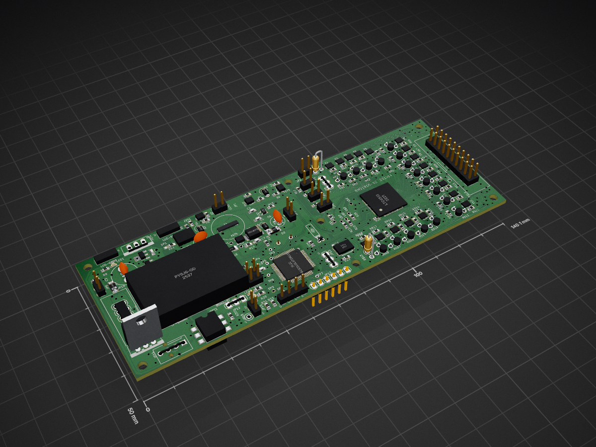
Bms1818 is an open-source printed circuit board by GliderWinchItems, from the GliderWinchItems/BMS repository on GitHub. It is a 2-layer board of 140.1 × 50 mm with 290 parts on 233 nets, routed with 2,325 tracks and 327 vias.
It is built around the ISO1042DW, MCP6006-E/OT and 74LVC1G14Z, with the H11L1S, MMSZ5245 and LDK320ADU120R among its other parts. Its parts include 57 resistors, 53 capacitors, 18 fuses, 10 diodes and 5 ICs. It belongs with the power boards of this library.


Battery Management System
This repo has directories for three BMS designs.
The original plan used a LTC6813-1 (18 cells), but when it came time to order the pcb, the part was no longer available. The TI BQ76952 (16 cells) was then found to be available in a few months so that design was completed. The testing of the first prototype with the BQA76952 turned up some unexplained failures, plus additional BQ76952 parts would not be available for approximately one year.
The ADBMS1818 chip became available and samples were to be shipped in a few weeks, and additional parts available from Mouser in several months. This gave rise to the second design. The delivery schedule changed and it would be about one year for samples and additional parts. This gave rise to a design based on the MAX14952. The designs differ mainly in the BMS chip. The same processor, STM32L431RxT6, is used and the features are nearly identical in the three designs, e.g. the trickle charger, CAN, and fan interfaces, etc. Much of the documentation for the BQ76952 board applies to all three designs.
| Qty | Value | Footprint | References |
|---|---|---|---|
| 24 | 0.1u | bms1818:C0603 | C7, C8, C100, C101, C104, C118, CC101, CC102, CC103, CC104, CC105, CC106, CC107, CC108, CC109, CC110 +8 |
| 23 | 3.3K | bms1818:R0603 | G5, R28, R31, R32, R116, R123, RG1, RG10, RG11, RG12, RG13, RG14, RG15, RG16, RG17, RG18 +7 |
| 18 | 10 | bms1818:R0603 | RR1, RR2, RR3, RR4, RR5, RR6, RR7, RR10, RR11, RR12, RR13, RR14, RR15, RR16, RR17, RR18 +2 |
| 18 | ~ | bms1818:SOT-23 | F1, F2, F3, F4, F5, F6, F7, F10, F11, F12, F13, F14, F15, F16, F17, F18 +2 |
| 17 | 33 | bms1818:RS-2,5-2 | RD2, RD3, RD4, RD5, RD6, RD7, RD8, RD10, RD11, RD12, RD13, RD14, RD15, RD16, RD17, RD18 +1 |
| 17 | SOLDPAD028 | bms1818:SOLPAD028 | CANH0, CANL0, RXD0, SP2, SP3, TP-GND0, TP-GNDA0, TP1, TP2, TXD0, U$2, U$3, U$4, U$6, U$7, UNK5V1 +1 |
| 12 | 10K | bms1818:R0603 | R9, R10, R14, R15, R18, R19, R21, R24, R30, R100, R102, R124 |
| 10 | 1M | bms1818:R0603 | R2, R3, R7, R12, R101, R104, R110, R128, R130, R131 |
| 8 | 1u | bms1818:C0603 | C2, C5, C102, C110, C111, C114, C121, C126 |
| 7 | @HOLE0, @HOLE1, @HOLE2, @HOLE3, @HOLE4, @HOLE5, @HOLE6 | ||
| 5 | 100K | bms1818:R0603 | R4, R13, R107, R109, R129 |
| 5 | 4.7u 25v | bms1818:C0805 | C112, C116, C119, C122, C125 |
| 5 | SOLDPAD0.6MM | bms1818:SOLPAD.6MM | TP3, TP4, TP5, TP6, TP7 |
| 4 | TBD | bms1818:R0603 | R20, R22, R23, R114 |
| 3 | 1 | bms1818:R0603 | BEAD0, R122, R127 |
| 3 | 1.2K | bms1818:R0603 | R17, R121, R125 |
| 3 | 270K | bms1818:R0603 | R1, R6, R8 |
| 3 | AP7380Y | bms1818:SOT89 | REG1, REG1A0, REG100 |
| 3 | H11L1S | bms1818:SMD-6 | OPT1, OPT100, OPT101 |
| 3 | NFET 20V | bms1818:SOT-23 | FET2, FET3, FET106 |
| 3 | PFET -20V | bms1818:SOT-23 | FET1, FET103, FET104 |
| 3 | ~ | bms1818:CHIP-LED0603 | LED1, LED2, LED3 |
| 2 | 0.1u 25v | bms1818:C0603 | C117, C120 |
| 2 | 1.8K | bms1818:R0603 | R103, R105 |
| 2 | 1N4148 | bms1818:DO41-10_VERT | D1, D2 |
| 2 | 22p | bms1818:C0603 | C105, C106 |
| 2 | 33 | bms1818:RS-2,5 | R$13, RD1 |
| 2 | 33p | bms1818:C0603 | C108, C109 |
| 2 | 4.7u 10v | bms1818:C0603 | C107, C123 |
| 2 | 470K | bms1818:R0603 | R29, R106 |
| 2 | 6.8K | bms1818:R0603 | R27, R111 |
| 2 | Dump2 | bms1818:1X02 | JP5, JP15 |
| 2 | MMSZ52 | bms1818:SOD80C | D3, D8 |
| 2 | NFET | bms1818:SOT-23 | FET100, FET101 |
| 2 | open | bms1818:R0603 | R120, R126 |
| 2 | ~ | bms1818:1X03 | JP4, JP12 |
| 1 | 0.1 | bms1818:M1206 | R16 |
| 1 | 0.1 | bms1818:R0805 | R119 |
| 1 | 0.1u 25v | bms1818:E5-8,5 | C3 |
| 1 | 100 | bms1818:R0603 | R26 |
| 1 | 100n | bms1818:C0603 | C103 |
| 1 | 10@25V | bms1818:ES-2,5L | C4 |
| 1 | 10M | bms1818:R0603 | R11 |
| 1 | 10n | bms1818:C0603 | C115 |
| 1 | 18K | bms1818:R0603 | R108 |
| 1 | 1K | bms1818:R0603 | R5 |
| 1 | 1N4148 | bms1818:SOD123 | D6 |
| 1 | 1N5357 | bms1818:ZENER-VERT | D5 |
| 1 | 1u 25v | bms1818:C0603 | C1 |
| 1 | 1u@100v | bms1818:ES-2,5L | C6 |
| 1 | 1u@100v | bms1818:C1206 | C113 |
| 1 | 3.9K | bms1818:R0603 | R25 |
| 1 | 33K | bms1818:R0603 | R115 |
| 1 | 4.7u | bms1818:C0603 | C124 |
| 1 | 4.7u 6.3 | bms1818:C0603 | CP101 |
| 1 | 4.7u 6.3v | bms1818:C0603 | CP100 |
| 1 | 47k | bms1818:R0603 | R113 |
| 1 | 6.8 | bms1818:R0603 | R117 |
| 1 | 68K | bms1818:R0603 | R118 |
| 1 | 7402 | bms1818:TSSOP14 | IC1 |
| 1 | 74LVC1G14 | bms1818:SOT-23 | IC100 |
| 1 | 8 MHz | bms1818:HC49_S | Q100 |
| 1 | AM6G1215SNZ | bms1818:DCDC7PINB | IC1B0 |
| 1 | DUMP | bms1818:1X02 | JP1 |
| 1 | FTDI | bms1818:1X06 | JP17 |
| 1 | ISO1042 | bms1818:SOIC-8 | U$8 |
| 1 | ISO1042-16PIN | bms1818:SO-16DW | IC2A0 |
| 1 | LDK320ADU120R | bms1818:SOT89 | REG3A0 |
| 1 | LM7812T | bms1818:TO220V | REG3B0 |
| 1 | LTC6813 | bms1818:TQFP64_PAD | U$5 |
| 1 | MBRS1100 | bms1818:SMB_1 | D7 |
| 1 | MCP1401|1416 | bms1818:SOT23-5 | IC101 |
| 1 | MCP6006 | bms1818:SC-70-5 | U$100 |
| 1 | MINUS | bms1818:SPADE_TAB | LUG-GND0 |
| 1 | NFET 100V | bms1818:TO220V | FET4 |
| 1 | NFET 100V si2324A | bms1818:SOT-23 | FET105 |
| 1 | OPEN? | bms1818:R0603 | R112 |
| 1 | PB | bms1818:1X02 | JP2 |
| 1 | PINHD-1X4-MOLEXKK | bms1818:1X4-MOLEXKK | JP14 |
| 1 | PINHD-2X10_KEYED | bms1818:2X10_KEYED | JP9 |
The 269 most common of 290 parts.
It measures 140.1 × 50 mm and has 2 copper layers, 1.6 mm thick.
290 parts, built around the ISO1042DW, MCP6006-E/OT, 74LVC1G14Z and H11L1S. The full list of its parts is on this page, with links to each part's symbol and footprint where PCBKit's library has them.
From the GliderWinchItems/BMS repository on GitHub, at the commit this page was made from: the board is hw/kicad/bmsbms1818-v2/bms1818_2/bms1818.kicad_pcb and its schematic hw/kicad/bmsbms1818-v2/bms1818.kicad_sch. PCBKit opens the board in the browser, with nothing to install.
Its repository states no licence, so its author keeps all rights: ask GliderWinchItems before reusing the design.


Quchaosheng/workbench-mobile-home-robot
Evidence-first runtime for a wheeled mobile household robot with bounded actions, replayable events, and fail-closed verification.

EmperorSmith/HomePowerBank
This project is a combined hardware-software effort around designing a control / management system for a home power bank.

hex-inverter/VVVF_motor_drive
The inspiration for this project came from a very characteristic sound in Amsterdam metro trams. During acceleration or braking they make a "shifting gears" sound even though the motors are electric (this sound can also…

GliderWinchItems/bmsmot
The contactor function measures the high voltage using a STM32L431RCT6, ground isolated and communicates readings to the main processor via uart with opto-isolator.
