2 layers33.2 × 34.6 mm
 GLGPrograms/tinyDiskII12
Homemade floppy disk emulator for Apple II series computers
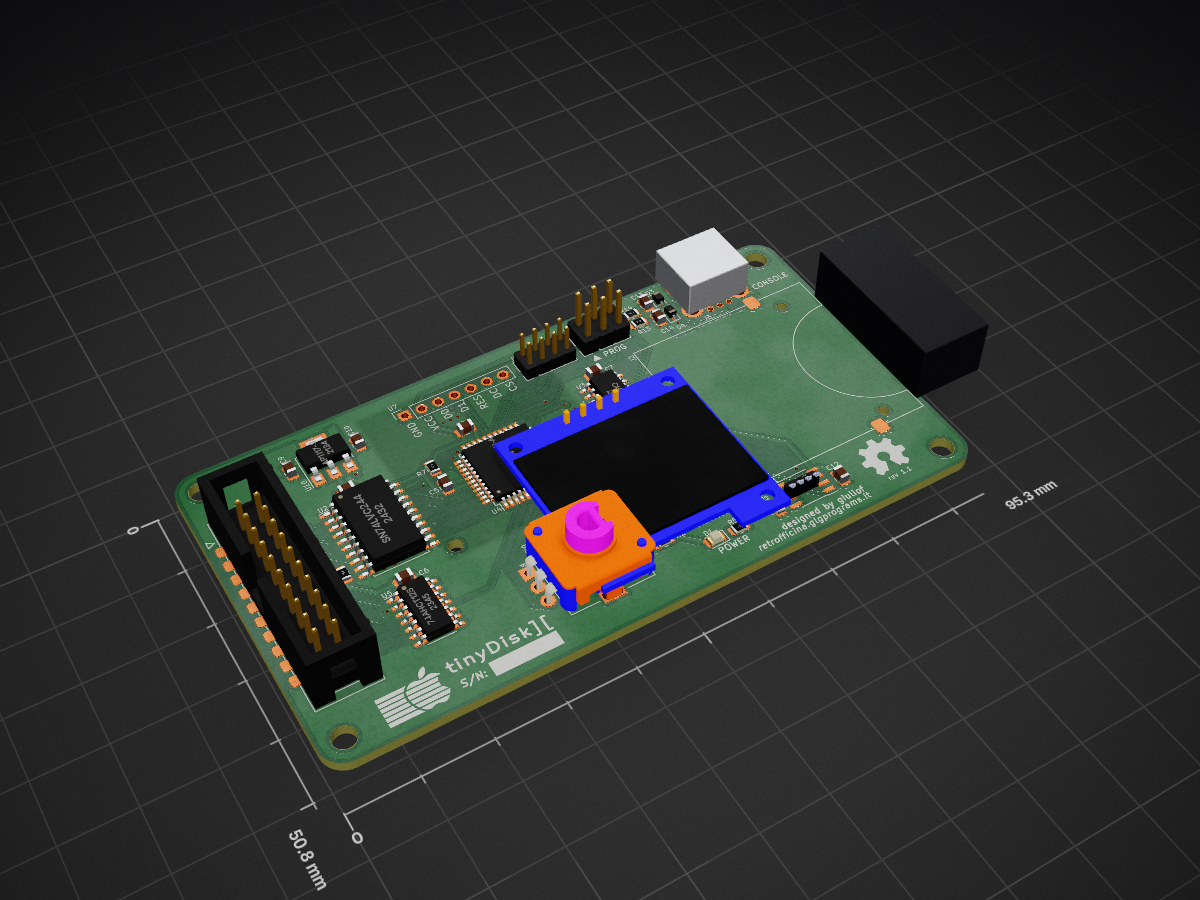
TinyDiskII is an open-source printed circuit board by GLGPrograms, from the GLGPrograms/tinyDiskII repository on GitHub, published under the GPL-3.0 licence. It is a 2-layer board of 95.3 × 50.8 mm with 52 parts on 81 nets, routed with 462 tracks and 58 vias.
It is built around the ATXMEGA16A4U-AU, 74AHCT125D and CH340C, with the SN74LVC244AN among its other parts. Its parts include 15 resistors, 6 ICs, 4 diodes, 4 connectors and 3 capacitors. It belongs with the retro computing and games boards and the AVR (ATmega, ATtiny) boards of this library.


Homemade floppy disk emulator for Apple II series computers
:warning: Work in progress: read carefully the README before trying to reproduce this project!

tinyDiskII is able to simulate an Apple Disk II both in reading and writing. Disk images are stored into a FAT16 formatted SD Card. Each disk image must be a DOS 3.3 floppy image, saved as .NIC. A cross platform .NIC <-> .DSK conversion tool will be available soon on this repository. Floppy formatting is currently not supported, but it is currently under developement.
| Reference(s) | Description | Notes |
|---|---|---|
| C1, C2, C3, C4, C5, C6, C8, C9, C10, C11, C12 | 0805 100n Capacitor | |
| D1, D2 | 0805 Red LED | |
| J1 | 2x3 male jumper | ICSP connector |
| J2 | SMD SD Card slot | |
| J3 | THT USB B Mini connector | Mount for USB debug |
| J4 | 2x10 male connector | DiskII connector |
| R5, R6 | 330 | |
| R2, R3, R4, R7, R8, R9, R10, R11, R12, R15 | 10k | |
| R13, R14 | 0 | Replaced with a bridge |
| SW1 | RotaryEncoder with switch | |
| U2 | SN74LVC244 | 5V tolerant buffer |
| U3 | CH340C | Mount for USB debug |
| U4 | ATxmega16A4U-A | MCU |
| U5 | 74AHCT125 | Level shifter |
| U7 | 0.96" OLED I2C | 7-pin model |
| U10 | AP1117-33 | 3v3 linear regulator |
| Reference(s) | Feature |
|---|---|
| U1 | Flash/EEPROM interface |
| C12 | " |
| R1 | " |
| C13, C14 | USB ESD |
| R13, R14 | " |
| D3, D4 | " |
| C7 | USB self reset |
| J5 | Debugging connector |
:warning: Schematics and PCB layout can be found in
/schematicsfolder. Please note that I had physically implemented only rev1.0, which requires some hardware patches. The issues were fixed in rev1.1, but I never put it into production. Build it at your own risk.
Firmware source code is in /firmware folder.
Code can be compiled on a linux/wsl machine through make command.
Make sure you have make and avr-gcc toolchanin installed.
Output binary will be generated as /firmware/output/tinyDiskII.hex.
In /firmware/tests there are some unit tests that can run on host system.
They can be compiled and executed with:
cd firmware/tests
cmake -B build .
cd build
cmake --build .
./tinyDiskII-testsThe serial interface is mainly used for application logging. If no OLED display is detected, the serial interface is enabled for receiving commands. If the OLED is connected, the command interpreter is disabled to avoid conflicts.
The following table resumes the available commands.
| Command | Arguments | Description |
|---|---|---|
INIT | none | Initialize the SD Card (1) |
CWD | dirname | Change woring directory to dirname |
UP | none | Change working director to the parent directory |
LST | none | List files and directory in the current working directory |
SET | filename | Select filename, in current working directory, as currently inserted disk (2) |
REM | none | Remove currently inserted disk |
FAT | upto | Prints FAT entries of selected file up to index upto (debug) |
INFO | t s | Prints .NIC file informations about sector s in track t (debug) |
rev1.0: first version
rev1.1: fixes the issues present in rev1.0:
| Qty | Value | Footprint | References |
|---|---|---|---|
| 11 | 100n | Capacitor_SMD:C_0805_2012Metric | C?, C1, C3, C4, C5, C6, C8, C9, C10, C11, C12 |
| 10 | 10k | Resistor_SMD:R_0805_2012Metric | R2, R3, R4, R7, R8, R9, R10, R11, R12, R15 |
| 4 | MountingHole | MountingHole:MountingHole_3.2mm_M3 | H1, H2, H3, H4 |
| 3 | C | Capacitor_SMD:C_0805_2012Metric | C7, C13, C14 |
| 2 | - | Diode_SMD:D_SOD-323 | D3, D4 |
| 2 | 10 | Resistor_SMD:R_0805_2012Metric | R13, R14 |
| 2 | 330 | Resistor_SMD:R_0805_2012Metric | R5, R6 |
| 2 | LED | LED_SMD:LED_0805_2012Metric | D1, D2 |
| 1 | 74AHCT125 | Package_SO:SOIC-14_3.9x8.7mm_P1.27mm | U5 |
| 1 | AP1117-33 | Package_TO_SOT_SMD:SOT-223-3_TabPin2 | U10 |
| 1 | APPLEII_DISK_CONNECTOR | Connector_IDC_SMDTHT:IDC-Header_2x10_P2.54mm | J4 |
| 1 | ATxmega16A4U-A | Package_QFP:TQFP-44_10x10mm_P0.8mm | U? |
| 1 | AVR-PDI-6 | Connector_PinHeader_2.54mm:PinHeader_2x03_P2.54mm_Vertical | J? |
| 1 | CH340C | Package_SO:SOIC-16_3.9x9.9mm_P1.27mm | U3 |
| 1 | Ext | Connector_PinHeader_2.00mm:PinHeader_2x04_P2.00mm_Vertical | J5 |
| 1 | GraphicSymbol | Vintage:Apple_Logo | SYM1 |
| 1 | Logo_Open_Hardware_Small | Symbol:OSHW-Symbol_6.7x6mm_SilkScreen | SYM2 |
| 1 | MX25R3235FM1xx0 | Package_SO:SOP-8_3.9x4.9mm_P1.27mm | U1 |
| 1 | OLED_MULTI | ModuleEnhanced:OLED_MULTI | U7 |
| 1 | R | Resistor_SMD:R_0805_2012Metric | R1 |
| 1 | RotaryEncoder_Switch | DeviceEnhanced:RotaryEncoder_Switch | SW1 |
| 1 | SD_Card | Connector_Card_Enhanced:SDCard | J2 |
| 1 | SN74LVC244 | Package_SO:SOIC-20W_7.5x12.8mm_P1.27mm | U2 |
| 1 | USB_B_Mini | Connector_USB_Enhanced:USB_Mini-B_THT_generic | J3 |
It measures 95.3 × 50.8 mm and has 2 copper layers, 1.6 mm thick.
52 parts, built around the ATXMEGA16A4U-AU, 74AHCT125D, CH340C and SN74LVC244AN. The full list of its parts is on this page, with links to each part's symbol and footprint where PCBKit's library has them.
From the GLGPrograms/tinyDiskII repository on GitHub, at the commit this page was made from: the board is schematics/tinyDiskII.kicad_pcb and its schematic schematics/tinyDiskII.kicad_sch. PCBKit opens the board in the browser, with nothing to install.
Its repository publishes it under the GPL-3.0 licence: you may reuse it on that licence's terms (keep the author's notice, and for a copyleft licence share your changes alike).


WojciechNowakowski/PCB-designs
Container for PCB designs created by me (in KiCad software mostly)


auselia/adc_test_board
ADS7057 test board: perfboard SMA -> filters -> ADC + wake comparator -> ZedBoard PMOD (KiCad 10, JLCPCB-ready)


gloveboxes/pcb-z80
pcb-z80 is a container-only, repeatable build of the four-layer Z80 ROMless SBC PCB engineering design. It regenerates the KiCad schematic, places the four-layer board, routes a fresh Specctra session, imports and fills…