
4 layers205.5 × 152 mm

DAPLink (CMSIS-DAP) compatible hardware
GlassLink is an open-source printed circuit board by glassboard-dev, from the glassboard-dev/gl-glasslink-hardware repository on GitHub, published under the CC-BY-SA-4.0 licence. It is a 2-layer board of 37 × 13 mm with 37 parts on 52 nets, routed with 299 tracks and 52 vias.
It is built around the LPC11U35FHI33/501Y, SN65220DBV and ECS-120-20-30B-TR, with the FTSH-105-01-F-DV-K among its other parts. Its parts include 16 resistors, 8 capacitors, 3 ICs, 3 diodes and 2 connectors. It belongs with the NXP (LPC, Kinetis, i.MX RT) boards of this library.


CMSIS-DAP Compatible Debugger & Programmer for ARM M-Cores

The Glasslink hardware is currently developed in the open source ECAD software KiCAD. The board was created using as many of the included component symbols and footprints as possible. Any custom components are located in the Glasslink.lib and Glasslink.pretty files. Additional 3D models were also added to the designa and can be found in the models folder. The KiCAD Teardrops extension was used to add teardrops to SMD pads and Vias.
Once you have a physical piece of hardware in hand, you can begin flashing and setting the device up for your use. The Glasslink hardware is intended to run the open-source firmware DAPLink which supports Drag-N-Drop flashing of certain targets, CDC serial port, CMSIS-DAP WinUSB & HID debug channel as well as WebUSB debug channels. The tested Firwmare has been built using the current develop branch (as of 12/10/2021) using the GNU Arm Embedded Toolchain 10-2020-q4-major toolchain. More information on building standalone firmware or firmware intended for a specific target (utilizing MSC/Drag-N-Drop) - see here.
Once you are ready to flash firmware to the DAPLink hardware, you can utilize the built-in NXP USB ROM Bootloader. A fresh piece of hardware should enumerate immediately into the bootloader when the USB is plugged in. Otherwise, you can hold down the nRESET pushbutton while plugging in the USB. The ROM Bootloader will enumerate as a MSD labeled CRP_DISABLED.
On windows, to flash a piece of Glasslink hardware you can simply drag your compiled firmware onto the storage device found in File Explorer.
On linux, the dd command is used to write the firmware to your Glasslink hardware
sudo dd if=lpc11u35_if.bin of=/media/user/CRP\ DISABLD/firmware.bin conv=notruncThere are two common applications for utilizing the Glasslink debug probe: PyOCD and OpenOCD. Check the documentation for each on how to connect a probe, flash a target, debug, etc.
The Glasslink hardware enumerates not only as a CMSIS-DAP probe, but also as a CDC serial port. This port can be utilized to send UART/serial data from your Target to a connected Host PC. On Windows a new COM port should enumerate and on Linux a new ACM port should enumerate when the Glasslink probe is connected.
To connect the Glasslink serial lines to your targets UART, please reference the 10pin ARM header pinout below. The current design assumes that you are creating your target hardware and have the ability to route your UART pins to the "unused" pins of the SWD header.
NOTE - The UART switching for TX<->RX and RX<->TX is done for you on the Glasslink hardware. The target TX pin sould go to pin 9 of the 10pin ARM header.
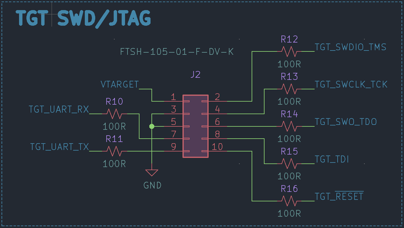
| Qty | Value | Footprint | References |
|---|---|---|---|
| 7 | 100R | Resistor_SMD:R_0402_1005Metric | R10, R11, R12, R13, R14, R15, R16 |
| 4 | 0.1u | Capacitor_SMD:C_0402_1005Metric | C4, C5, C6, C8 |
| 3 | 10k | Resistor_SMD:R_0402_1005Metric | R1, R2, R9 |
| 3 | 470R | Resistor_SMD:R_0402_1005Metric | R3, R4, R5 |
| 3 | Fiducial | Fiducial:Fiducial_0.5mm_Mask1mm | FID1, FID2, FID3 |
| 2 | 10u | Capacitor_SMD:C_0402_1005Metric | C3, C7 |
| 2 | 20p | Capacitor_SMD:C_0402_1005Metric | C1, C2 |
| 2 | 22R | Resistor_SMD:R_0402_1005Metric | R6, R7 |
| 1 | 1.5k | Resistor_SMD:R_0402_1005Metric | R8 |
| 1 | AP2204K-3.3 | Package_TO_SOT_SMD:SOT-23-5 | U2 |
| 1 | BLUE | LED_SMD:LED_0603_1608Metric | D2 |
| 1 | ECS-120-20-30B-TR | Crystal:Crystal_SMD_5032-4Pin_5.0x3.2mm | Y1 |
| 1 | FTSH-105-01-F-DV-K | Connector_PinHeader_1.27mm:PinHeader_2x05_P1.27mm_Vertical_SMD | J2 |
| 1 | GREEN | LED_SMD:LED_0603_1608Metric | D3 |
| 1 | LPC11U35FHI33_501 | GlassLink:QFN-32_EP_6.2x6.2_Pitch0.5mm | U3 |
| 1 | RED | LED_SMD:LED_0603_1608Metric | D1 |
| 1 | SN65220 | Package_TO_SOT_SMD:SOT-23-6 | U1 |
| 1 | SW_Push | Button_Switch_SMD:Panasonic_EVQPUL_EVQPUC | SW1 |
| 1 | USB_C_Receptacle_USB2.0 | Connector_USB:USB_C_Receptacle_GCT_USB4085 | J1 |


pypilot/pypilot_mfd
lcd display for various types of marine data including nmea0183, signalk and pypilot


OklahomaOpenSourceHardware/Oklahoma-Open-Hardware-Mechanical-Keyboard
Oklahoma themed open source hardware licensed keyboard from the Oklahoma community


juniper-garden/twig_temp_humidity_sensor
Hardware files for the temperature and humidity sensor

rimio/cat-a-hack
Prototyping board for PC/μC to transceiver isolation.
It measures 37 × 13 mm and has 2 copper layers, 1.6 mm thick.
37 parts, built around the LPC11U35FHI33/501Y, SN65220DBV, ECS-120-20-30B-TR and FTSH-105-01-F-DV-K. The full list of its parts is on this page, with links to each part's symbol and footprint where PCBKit's library has them.
From the glassboard-dev/gl-glasslink-hardware repository on GitHub, at the commit this page was made from: the board is GlassLink.kicad_pcb. PCBKit opens the board in the browser, with nothing to install.
Its repository publishes it under the CC-BY-SA-4.0 licence: you may reuse it on that licence's terms (keep the author's notice, and for a copyleft licence share your changes alike).